Dek-265GSX-User-Manual.pdf.pdf - 第55页
8. Remove the head prop. Lower the printhead using two button control. 9. Press the System button. 10. Select Board Width (F5). Board Width 11. Select Board Stop (F4). The camera moves to the board stop position. The boa…
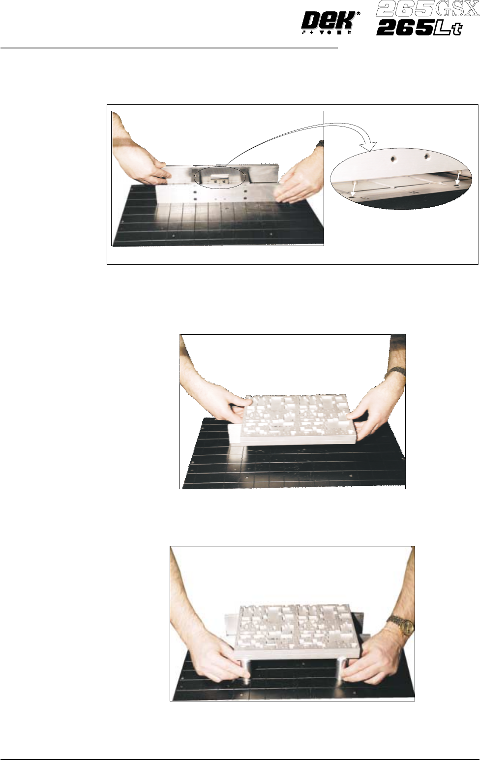
5. Fit the tooling tower to the manual tooling plate. Ensure the dowels on the
front edge of the tooling tower base are correctly seated in the holes in the
front edge of the manual tooling plate.
6. Verify the plate assembly orientation and fit the assembly to the tooling
tower. Ensure the dowels of the plate assembly are correctly seated in the
holes in the tooling tower.
7. If required, slide the additional magnetic pins beneath the plate assembly to
fully support it when printing wide boards.
1.38 User Manual Software Version 6
MACHINE PROGRAMMING
STAGE 6C
View on Rear of Tooling Plate
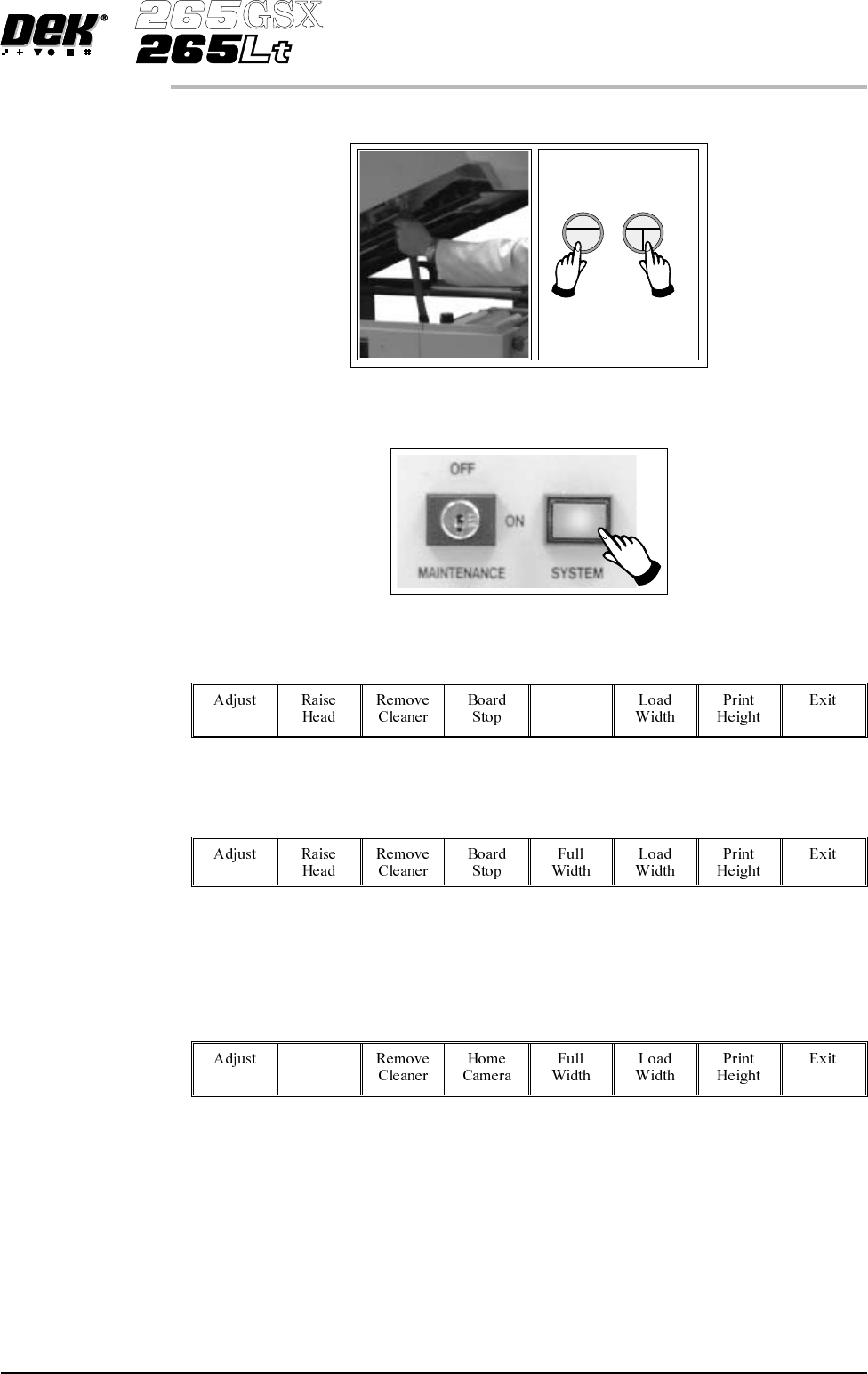
8. Remove the head prop. Lower the printhead using two button control.
9.
Press the System button.
10.
Select Board Width (F5).
Board
Width
11.
Select Board Stop (F4).
The camera moves to the board stop position. The board stop on the camera
extends.
12.
Select Raise Head (F2).
Raise
Head
Software Version 6 User Manual 1.39
MACHINE PROGRAMMING
STAGE 6C
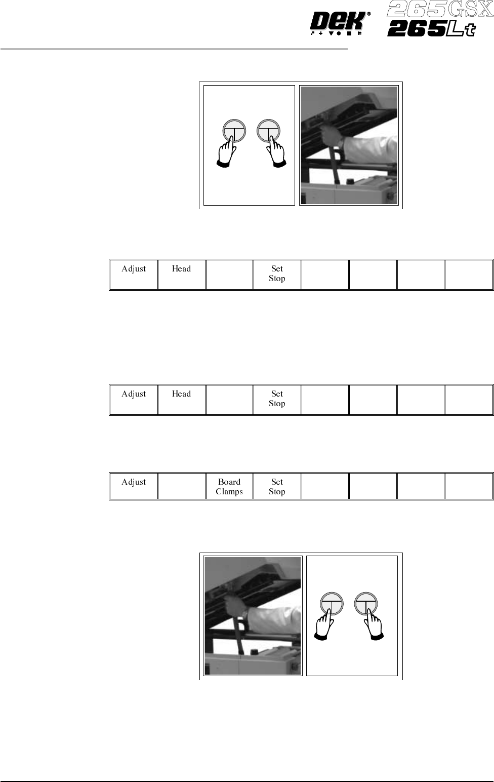
13. Raise the printhead using two button control. Fit the head prop.
14.
Select Board Clamps (F3), to open the clamps.
Board
Clamps
15. Slide a board along the rails to abut the board stop.
16.
Select Board Clamps (F3), to close the clamps.
Board
Clamps
17.
Select Head (F2).
Head
18. Remove the head prop. Lower the printhead using two button control.
1.40 User Manual Software Version 6
MACHINE PROGRAMMING
STAGE 6C