Dek-265GSX-User-Manual.pdf.pdf - 第218页
Move Camera Y Axis Using Jog Buttons Selecting this option enables the right jog button to drive the camera in the Y axis to the rear at slow speed and using the left jog button drives the camera forward, stopping immedi…

NOTE
These parameters are used in diagnostics only and have no affect on the product
board file.
Home Camera
X Axis
Selecting this option drives the Camera X carriage to find its datum position as
determined by it’s home sensor.
Home Camera
Y Axis
Selecting this option drives the Camera Y carriage to find its datum position as
determined by it’s home sensor.
Camera Axis to
Fiducial 1 Position
Selecting this option drives both X and Y carriages to the position set by the
fiducial 1 X and Y coord parameters.
Camera Axis to
Fiducial 2 Position
Selecting this option drives both X and Y carriages to the position set by the
fiducial 2 X and Y coord parameters.
Camera Axis to
Fiducial 3 Position
Selecting this option drives both X and Y carriages to the position set by the
fiducial 3 X and Y coord parameters.
Drive to Board Stop
Position
Selecting this option drives both X and Y carriages to the position of the board
stop for the current product.
Restore Default
Reference Position
Selecting this option restores the reference position stored as a default in
software.
Drive to Reference
Position
Selecting this option enables drive to both X and Y carriages, to the position set
by the camera X and Y reference parameters.
Set Reference
Position
Selecting this option alters the Printer Configuration file after the camera has
been positioned so that it is viewing the reference mark on the front rail. On
selection of this option the Menu Bar displays Confirm, pressing this key alters
the printer configuration file. This is used in conjunction with Move camera X
and Y axes.
Move Camera X
Axis Using Jog
Buttons
Selectingthisoptionenables the right jog button to drive the camera in the Xaxis
to the left at slow speed and the left jog button drives the camera right, stopping
immediately the button is released, (see Note).
NOTE
This is a physical movement of the camera, not as displayed on the monitor.
Software Version 6 User Manual 5.23
DIAGNOSTICS
CAMERA AXES

Move Camera Y
Axis Using Jog
Buttons
Selectingthisoptionenables the right jog button to drive the camera in the Yaxis
to the rear at slow speed and using the left jog button drives the camera forward,
stopping immediately the button is released, (see Note above).
Initialize Vision
System
Selecting this option initializes the frame grabber board and it displays a live
image on the vision monitor and a super-imposed box graphic.
Cycle Camera
System
Selecting this option starts a continuous cycle of driving the camera X and Y
carriages to each of the following positions in sequence, dwelling for 2 seconds
at each point, locating the fiducial at each fiducial position, displaying the
returned location and repeating the cycle. The cycle is as follows:
1. Home
2. Fiducial 1
3. Fiducial 2
If the data logging is enabled the fiducial co-ordinates are appended to
C:\PRINTER\CAMERA.DAT file. This continuous cycle is terminated by
selecting the stop key or when the set cycle count has been reached (50).
Cycle count Displays the count when the module is being cycled.
5.24 User Manual Software Version 6
DIAGNOSTICS
CAMERA AXES
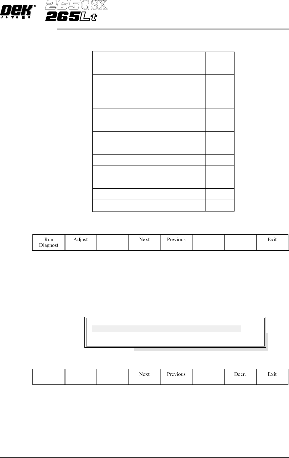
RAIL SYSTEM The Rail System diagnostic module contains the following:
Home Rail Width
Drive Rail to Board Width
Drive Rail Width using Two Button Control
Drive Belts using Two Button Control
Toggle Board Clamp On/Off
Toggle Board Stop On/Off
Cycle Board on Belts
Cycle Board Clamp
Cycle Rails
Board Stop in Position On/Off
Board at Stop On/Off
Board at Left On/Off
Board at Right On/Off
Cycle Count
The menu bar changes to the following:
RunDiagnost activates the diagnostic function, as selected by thehighlightbar.
Next/Previous keys move the highlight bar up and down the list of selectable
diagnostic functions.
Exit returns operation to the module diagnostics page.
Adjust opens the following window:
The menu bar changes to the following:
Incr.
Next/Previous keys move the highlight bar up and down the list of diagnostic
parameters.
Incr./Decr. keys change the value of the selected diagnostic parameter.
Exit returns operation to the rail system diagnostics page.
Software Version 6 User Manual 5.25
DIAGNOSTICS
RAIL SYSTEM
Rail System Test Parameters
BOARD WIDTH
CYCLE COUNT
250.0
50
mm
Cycles