Dek-265GSX-User-Manual.pdf.pdf - 第39页
4. Use the Incr. and Decr. keys (F6 - F7), or the forward slash key (/) on the keyboard, to change the parameter value. Incr. Decr. 5. Select Save (F2). The message ‘Saving fiducial data - Please wait Board data file sav…
STAGE 6A
Tooling Setup - Magnetic Pillars
CAUTION
BOARD CLAMPS. Care must be taken to ensure that the board clamps
are not damaged when removing or replacing tooling.
Board Stop Setting up the board stop position is automatically done using the board
dimensions previously setin the boardparameter file. If adjustment is necessary
proceed as follows:
1.
Select Change Tooling (F6).
Change
Tooling
The Change Tooling Parameters window is displayed:
NOTE
If the remote board stop is fitted the Board Stop X and Board Stop Y parameters
are replaced by Remote Board Stop X.
These parameters are automatically calculated from the board size parameters
that were entered in the product file. If they need adjustment to re-position the
board stop for any reason, ie any routing on the board edge or a badly positioned
image on the screen, this can be done now.
2.
Select Adjust (F1).
Adjust
3.
Use the Next and Previous keys (F4 - F5) to highlight each parameter.
Next Previous
1.22 User Manual Software Version 6
MACHINE PROGRAMMING
STAGE 6A
WARNING
BOARD CLAMPS. EXTREME CARE MUST BE EXERCISED WHEN
WORKING IN THE TOOLING AREA OF THE MACHINE TO AVOID
INJURY. THE FOILS ON THE FRONTAND REAR BOARD CLAMPS
AREVERYSHARP.
Change Tooling Parameters
BOARD WIDTH
BOARD STOP X
BOARD STOPY
216.0
125.0
142.6
mm
mm
mm
4.
Use the Incr. and Decr. keys (F6 - F7), or the forward slash key (/) on the
keyboard, to change the parameter value.
Incr. Decr.
5.
Select Save (F2). The message ‘Saving fiducial data - Please wait
Board data file saved’ is displayed.
Save
6.
Select Exit (F8).
Exit
Magnetic Pillars 1.
Select Board Stop (F4).
The camera moves to the board stop position. The board stop on the camera
extends.
2.
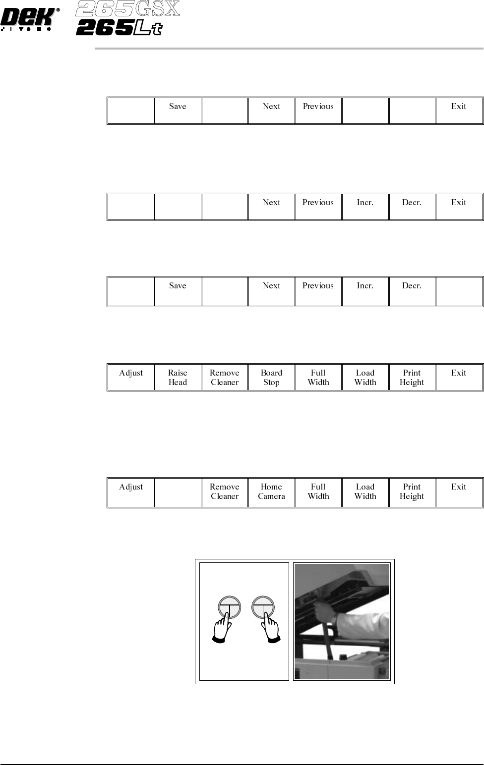
Select Raise Head (F2).
Raise
Head
3. Raise the printhead using two button control. Fit the head prop.
Software Version 6 User Manual 1.23
MACHINE PROGRAMMING
STAGE 6A
4.
Select Board Clamps (F3), to open the clamps.
Board
Clamps
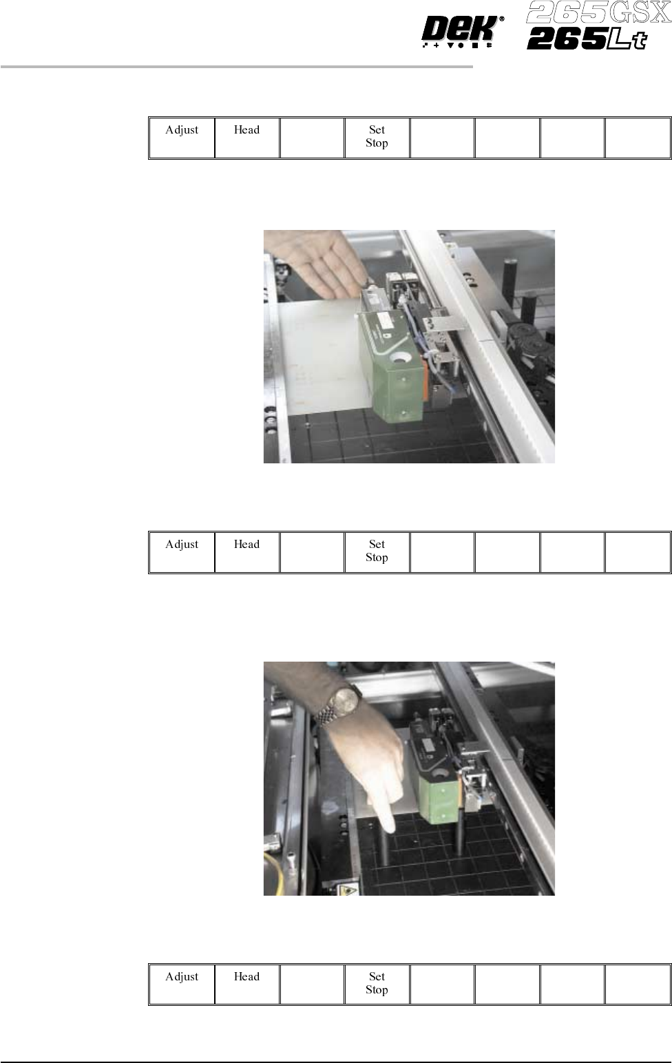
5. Slide a board along the rails to abut the board stop.
6.
Select Board Clamps (F3), to close the clamps.
Board
Clamps
7. Using the board as a reference, position the outermost support pins on the
rising table under the board.
8.
Select Board Clamps (F3), to open the clamps.
Board
Clamps
1.24 User Manual Software Version 6
MACHINE PROGRAMMING
STAGE 6A