00196608-01_AI_Stationaere_Kamera_Typ33_36_de_en.pdf - 第105页
Installation Stationary Camera Typ e 33/36 Stationäre Kamera Typ 33/36 105 3 Installation NOTICE Usage, differences b etween the cameras The type 33 stationary c ameras can be installed in SX and X ser ies, D3 and D1 SIP…

Brief Description
Tools and Equipment Required SIPLACE SX 4
104 Stationary Camera Type 33/36 Stationäre Kamera Typ 33/36
2.3.5 SIPLACE SX 4
Installation kit: stationary camera type 33 an SX4 [00519828-xx]
2.4 Tools and Equipment Required
▪ Set of Allen keys
▪ Allen key with T-handle size 5 and 6
▪ Set of screwdrivers
▪ Universal pliers
▪ Microfiber cloth for cleaning optical assemblies
▪ For cameras up to and including FS04: 2x DIN913-M6x50 (set screws) [03005958-xx]
▪ Calibration tool version 3 [03010565-xx]
▪ Nozzle/ZP correction P&P [03008862-xx] (for calibration up to SW705.02)
▪ 10x self-adhesive base for cable ties [03064015-xx]
▪ 10x cable ties, B=2.5 mm, L=102 mm, Panduit [00308458-xx]
▪ Service manual for your machine
▪ Circuit diagrams for your machine where necessary
▪ Assembly instructions "reject bin query X series/D3/SX4, DE+EN" [00194716-xx] or
Assembly instructions "reject bin query SX1/SX2, DE+EN" [00196615-xx]
2.5 Required Working Time
The complete installation procedure takes between 40 and 80 minutes, depending on the machine type,
installation location and whether the COT insert needs to be moved or not.
Quantity Designation Item No.
2 Distance plate for IC camera SX4 03080912- xx
2 ISO7379-8x40-12.9 03005648- xx
2 ISO 4762 - M 6 x 50-A2-70 03042580- xx
4 ISO 4762 - M 6 x 25-A2-70 03042575- xx
1 Component camera, stationary, P&P (type 33) 55 x 45, digital 03016339- xx
1 Waste box TwinHead SX4 assembly
This contains:
03082159- xx
1 Fixture bracket module assembly 03081981- xx
1 Reject bin assembly 03072806- xx
4 DIN7984-M6x12-A2-70 03081847- xx
1 Holder for reject bins P001 03063283- xx
1 Assembly instructions "stationary camera type 33/36" DE+EN 00196608- xx
2 DIN913-M6x50 (set screws) 03005958- xx
NOTICE
Second person
You might find it advisable to enlist the help of a second person for certain tasks.
Installation
Stationary Camera Type 33/36 Stationäre Kamera Typ 33/36 105
3 Installation
NOTICE
Usage, differences between the cameras
The type 33 stationary cameras can be installed in SX and X series, D3 and D1 SIPLACE ma-
chines; type 36 cameras can be installed in D1 machines. The camera design and the assem-
bly procedure for each camera is generally the same for the individual machines. Any
differences will be explicitly indicated in this guide.
CAUTION
Do not hold or carry the camera by its electronics unit.
The camera electronics assembly is a sensitive unit and can be easily damaged.
► Only hold or carry the camera by its metal frame.
► Always pull the illumination unit carefully up and off.
► The metal housing must always be hooked out of the lower section of the camera.
NOTICE
The upper section of the camera has a fixed assignment to the bottom section of the camera!
The upper section of the camera may not be used with a different bottom section. Both the up-
per and lower sections are mechanically and electrically coordinated and may not be ex-
changed for use with other cameras.
► The serial and version numbers of the top and bottom sections of the camera must be iden-
tical.
Installation
General Preparations
106 Stationary Camera Type 33/36 Stationäre Kamera Typ 33/36
3.1 General Preparations
The following tasks must be performed irrespective of the machine type:
► Create a data backup file for the existing machine configuration. (Hosts.txt, MaData.zip, MaDataIn-
fo.zip, Services.txt)
► Perform a machine data backup run.
► Save the complete SRCMA folder under a different name.
► Change over to the Service menu and select "Settings --> Machine Configuration". For detailed in-
structions about how to configure the camera, refer to the Online Help.
► Configure the new camera (standard camera type 33) in the machine configurator and save the data.
► Remove the component trolley/WPC from the camera installation position.
► Switch off the machine and secure it to prevent unauthorized reactivation. Observe the instructions
in section "1.2 Preparatory Work..." [ ➙ 93].
► Remove the waste tape chute. This is either screwed or hooked into place, depending on your ma-
chine.
► Change the machine configuration for the new camera in SIPLACE Pro.
► Perform placement program optimization for the line.
Configuration of stationary camera with SIPLACE Pro
See also
1.2 Preparatory Work... [ ➙ 93]
NOTICE
Camera configuration
For detailed instructions about how to configure the camera, refer to the SITEST Online Help
at "Settings - Settings for Placement Head".
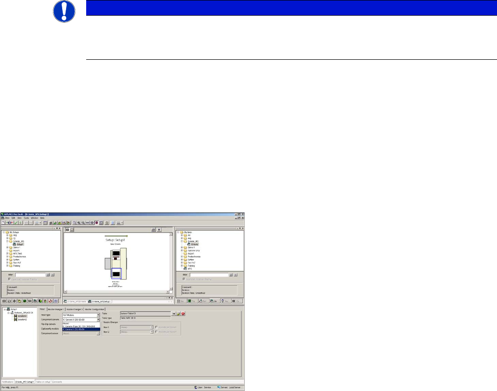
Configuration of stationary camera (using example of D1)
► Switch over to "Setup-Location-Head tab" and enter
the P&P head.
► Re-optimize the setup in SIPLACE Pro.