00196608-01_AI_Stationaere_Kamera_Typ33_36_de_en.pdf - 第146页
Installation Installation on SX4 Machines Electrical Connections 146 Stationary Camera Type 33/36 Stationäre Kamera Typ 33/ 36 Installation with set screws (for camera type 33 up to version 05, type 36 up to version 03) …
Installation
Mechanical Assembly Installation on SX4 Machines
Stationary Camera Type 33/36 Stationäre Kamera Typ 33/36 145
Installing the camera
Installation with keyhole (for camera type 33 from version 06, type 36 from version 04)
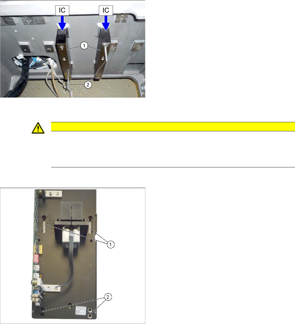
► Fit the two mounts (1) with 2 screws each to the ma-
chine frame. Make sure that the side labeled "IC" is at
the top.
► For installation with set screws only (see below):
Screw two set screws (2) (with the Allen key side on
the outside) into the mounts as an assembly aid.
CAUTION
Observe the installation height
When fitting the camera, observe the correct installation height. Othwerwise there is a risk of
head crash!
► Please also observe section "4.1 Installation Height of the Stationary Camera" [ ➙ 153].
► Tighten the two top screws until the shaft of the
screws protrudes approx. 15 mm over the mount.
► Hook the upper holes ((1) key holes) on the lower
section of the camera onto these two screws.
► Adjust the lower section of the camera to the correct
installation height, with the two lower screws (2) and
tighten all four screws.
Installation
Installation on SX4 Machines Electrical Connections
146 Stationary Camera Type 33/36 Stationäre Kamera Typ 33/36
Installation with set screws (for camera type 33 up to version 05, type 36 up to version 03)
3.5.3 Electrical Connections
► Pull the three connection cables for the IC camera through the opening and out of the machine
frame.
► Check the jumper setting. See also"4.2 Camera Coding and Connections" [ ➙ 155]
► To connect the camera, read section "4.2.1 Cameras Type 33 From Version 03 To 07, Cameras
Type 36 From Version 01" [ ➙ 155].
See also
3.5.3.1 Connecting the Hotlink Cable to the BoxPC [ ➙ 147]
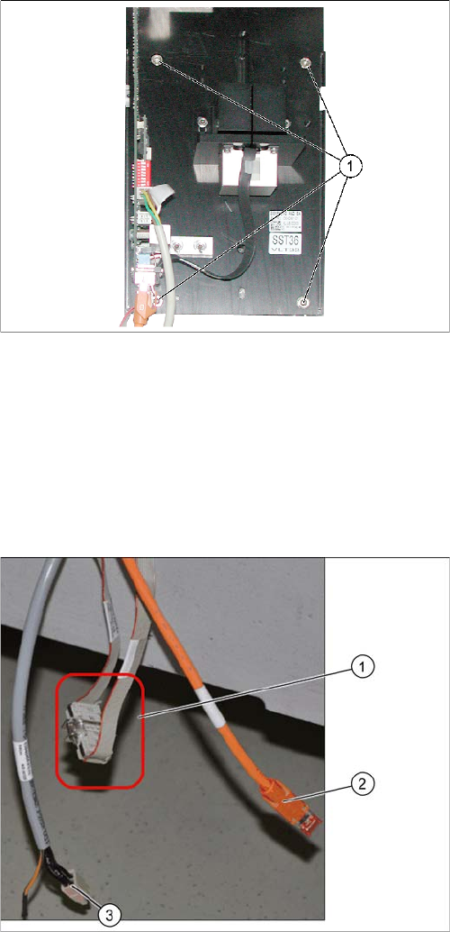
► Lift the lower section of the camera onto the two set
screws.
► Fix the lower section of the camera with 2 screws to
the unused screw openings (M6x35).
► Unscrew the two set screws again.
► Now fasten the right-hand side of the lower section of
the camera (in place of the two set screws). The low-
er section of the camera and the fiducial plate are
now fixed with four screws (1) to the machine frame.
CAN bus connection (X series – from serial no. B326)
► Connect the CAN bus cable (1), camera bus (2) and
voltage supply (3) to the camera. See also"4.6 Circuit
Diagrams SX4" [ ➙ 166]
► The CAN bus cable (03050239-xx) supplied in the
retrofitting kit is used to connect the CAN bus cable to
the camera. Separate the CAN bus cables from one
another at the coupling (1). Connect the adapter ca-
ble [03050239-xx] in-between so that you have two
additional CAN connectors available for the two sta-
tionary cameras.
Installation
Electrical Connections Installation on SX4 Machines
Stationary Camera Type 33/36 Stationäre Kamera Typ 33/36 147
3.5.3.1 Connecting the Hotlink Cable to the BoxPC
► Connect your camera cable as follows:
CAUTION
Never connect a LAN cable to the hotlink card!
This could damage the hotlink card.
NOTICE
Connection for stationary cameras
► Observe section "4 Appendix" [ ➙ 153] and the latest circuit diagrams for your machine.
► When installed, the version of your hotlink card can only be determined by the position of
the camera connection label and the order of CAM connections.
► The stationary cameras are always connected to CAM2 or CAM3.
► The camera cables are labeled with their relevant connection details according to the pat-
tern X*p*.
CAUTION
Correctly connecting the camera cable
► Make sure that you connect the cameras correctly. Observe the labels on the hotlink cards.
If you do not observe this, placement performance may be adversely affected. Pay partic-
ular attention to the different order of connections on the PCI-A24!
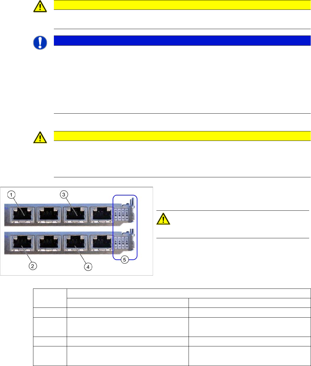
Hotlink card (PCI-A24 [03052135-xx])
The hotlink card is fitted in the SX4 as a default.
CAUTION!
Observe the order of camera connections (5)!
(1) and (3): Stationary cameras for placement area 1
(X2pr and X3pr)
(2) and (4): Stationary cameras for placement area 2
(X2ps and X3ps)
Hotlink cards
Card 1 (top) Card 2 (bottom)
CAM0 Gantry 1 - PCB/component camera Gantry 2 - PCB/component camera
CAM1 Not in use Gantry 2 - stationary cameras (IC/FC)
[03077048-xx] → cable X2ps
CAM2 Gantry 4 - PCB/component camera Gantry 3 - PCB/component camera
CAM3 Not in use Gantry 3 - stationary cameras (IC/FC)
[03077049-xx] → cable X3ps