00196608-01_AI_Stationaere_Kamera_Typ33_36_de_en.pdf - 第140页
Installation Installation on SX1/SX2 Machines Electrical Connections 140 Stationary Camera Type 33/36 Stationäre Kamera Typ 33/ 36 3.4.4 Electrical Co nnections Direct connection to the machine Connection to FC cameras (…
Installation
Mechanical Assembly Installation on SX1/SX2 Machines
Stationary Camera Type 33/36 Stationäre Kamera Typ 33/36 139
3.4.3.2 Installation of Camera with Keyhole (for Camera Type 33 from Version 06)
CAUTION
Observe the installation height
When fitting the camera, observe the correct installation height. Othwerwise there is a risk of
head crash!
► Please also observe section "4.1 Installation Height of the Stationary Camera" [ ➙ 153].
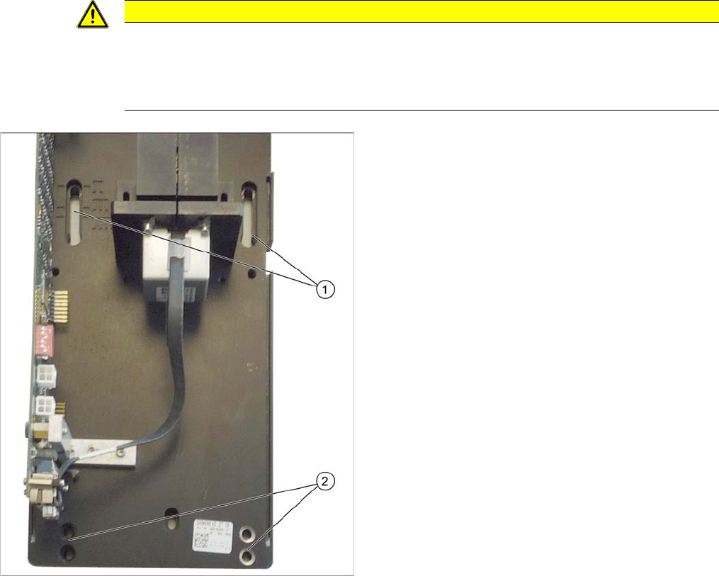
► Screw the two top fastening screws loosely into the
surface onto which the camera will be fitted later on.
The screws should be tightened enough to still allow
the camera to be easily hooked in.
► Carefully hook the top holes on the lower section of
the camera (1) onto the fastening screws.
► Fix the lower section of the camera with 2 screws to
the lower screw openings 2. Observe the required in-
stallation height.
► Tighten the two top fastening screws.
The lower section of the camera has now been fixed into
place.
Installation
Installation on SX1/SX2 Machines Electrical Connections
140 Stationary Camera Type 33/36 Stationäre Kamera Typ 33/36
3.4.4 Electrical Connections
Direct connection to the machine
Connection to FC cameras (type 25 with version 05)
If there is a version 05 FC camera present, the IC camera will be connected to this. From this version
onwards, the FC camera has a multiplexer, which provides the connections for the IC and FC cameras.
This enables you to operate a placement area with up to four stationary cameras.
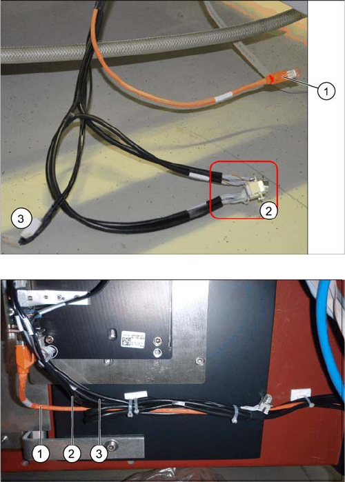
1. Camera cable (hotlink cable)
2. 2 x CAN bus cable (For IC and FC camera)
3. Power supply
The opening in the machine frame contains two CAN bus
cables (1), the camera cable (2) (hotlink cable) and the
power supply cable (3).
► Connect the camera cable (1), the CAN bus cable (2)
and the power supply cable (3) to the stationary cam-
era, according to the respective camera configura-
tion.
Installation
Electrical Connections Installation on SX1/SX2 Machines
Stationary Camera Type 33/36 Stationäre Kamera Typ 33/36 141
► Fix the incoming cables (camera bus, CAN bus, power supply) with the fastening element
[00316830-xx] and cable ties [00805141-xx] underneath the camera.
See also
3.5.3.1 Connecting the Hotlink Cable to the BoxPC [ ➙ 147]
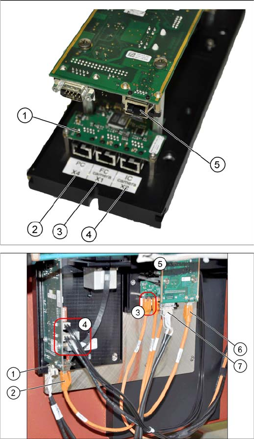
The multiplexer makes it possible to directly connect a
stationary camera (type 33/36) to the other stationary
camera (type 25).
1. Multiplexer
2. BoxPC input
3. Output for type 25 camera (FC camera)
4. Output for type 33/36 camera (IC camera)
5. Camera input
► Remove the upper part of the FC camera.
► Remove the FC camera housing.
► Disconnect the camera cable coming from the box
PC at the FC camera driver board (6) and reconnect
it to the multiplexer connection labeled PC.
► Underneath the FC camera you will find two unused,
short camera cables and the power supply cable
[03055298-xx], fixed with a cable tie to the support
plate. Use one short camera cable for the connection
between the multiplexer and the IC camera (2) and
the other one for the connection between the multi-
plexer and the FC camera driver board (6).
► Connect the power supply with the cable from the ret-
rofitting kit. To do this, connect the power supply ca-
ble [03055298-xx] to connection X4 or X5 on the IC
camera driver board (4) and to connection X4 on the
FC camera (5).
► Connect the CAN bus to connections (1) and (7).