00196608-01_AI_Stationaere_Kamera_Typ33_36_de_en.pdf - 第135页
Installation Installation position for SX1/SX2 Machines Installation on SX1/S X2 Machines Stationary Camera Typ e 33/36 Stationäre Kamera Typ 33/36 135 3.4.2 Installation position for SX1/SX2 Machines Installation positi…

Installation
Installation on SX1/SX2 Machines Moving COT Insert in SX1/SX2 Machines
134 Stationary Camera Type 33/36 Stationäre Kamera Typ 33/36
3.4 Installation on SX1/SX2 Machines
Required installation kits:
See"2.3 Scope of Delivery" [ ➙ 102]
Installation kit: stationary camera type 33 for CPP head fitted in SX1/SX2 machines [00519902-xx]
The stationary camera (type 33) is already included in the HRK for TwinHead used in SX1/SX2 ma-
chines.
3.4.1 Moving COT Insert in SX1/SX2 Machines
To access the stationary camera installation position, you may need to loosen the cutter and COT insert
and push them forwards.
NOTICE
DX1/DX2
Installation of the camera in DX1/DX2 machines follows the same procedure as that used for
SX1/SX2 machines. Any differences will be mentioned explicitly.
CAUTION
Dismantling the COT insert
► Read the sections "Removing the Cutter" and "Replacing the COT Insert" in the service
manual for your machine!
NOTICE
Mark the positions of the screws
► Mark the positions of all screws, to make clear assignment easier later on.
Installation
Installation position for SX1/SX2 Machines Installation on SX1/SX2 Machines
Stationary Camera Type 33/36 Stationäre Kamera Typ 33/36 135
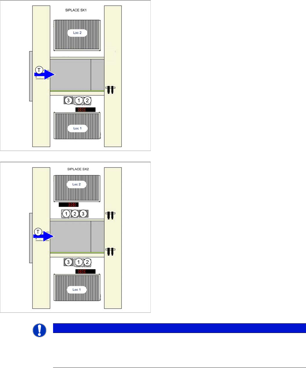
3.4.2 Installation position for SX1/SX2 Machines
Installation position of camera in the SX1
1. IC camera
2. FC camera/3D coplan module
3. Component reject bin
Loc 1/2 = location 1/2
Installation position of camera in the SX2
1. IC camera
2. FC camera/3D coplan module
3. Component reject bin
Loc 1/2 = location 1/2
NOTICE
TwinHead
The FC camera and the 3D coplan module are only possible together with a TwinHead. Only
one of these options can be fitted at the same location, meaning that either the FC camera or
the 3D coplan module can be used.
Installation
Installation on SX1/SX2 Machines Mechanical Assembly
136 Stationary Camera Type 33/36 Stationäre Kamera Typ 33/36
3.4.3 Mechanical Assembly
Preparatory Steps
► Unhook the plate from the empty tape duct.
► If there is already a stationary FC camera present at the location, carefully pull the illumination unit
up and out and unhook the metal housing of the lower camera section.
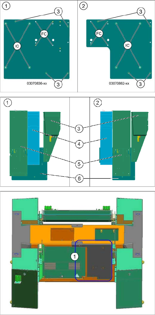
Support plates
1. Support plate location 1
2. Support plate location 2
3. Holes for fixing screws to the machine frame (4x
DIN912-M6x12-A2-70)
FC = FC camera (type 25)
IC = IC camera (type 33)
1. Location 1
2. Location 2
3. Reject bins
4. FC camera (type 25) with fiducial plate
5. IC camera (type 33)
6. Support plate
Surface for screwing to machine lower section
1. Surface for screwed fixture of support plate (location
2 shown here)