00196608-01_AI_Stationaere_Kamera_Typ33_36_de_en.pdf - 第133页
Installation Final Wo rk Assembly in a D1 Machine Stationary Camera Typ e 33/36 Stationäre Kamera Typ 33/36 133 3.3.4 Final Work ► Fit the camera hou sing. See a lso" 3.6.1 Assembling the Camera" [➙ 1 4 9 ] ► …
Installation
Assembly in a D1 Machine Electrical Connections
132 Stationary Camera Type 33/36 Stationäre Kamera Typ 33/36
See also
4.7 Circuit Diagrams D1 [ ➙ 168]
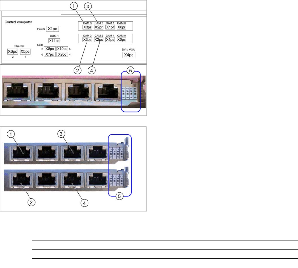
Hotlink card (PCI-A14 [03032343-xx])
The hotlink card is installed as a default with the box PC
627.
When installed, the version of the hotlink cards can only
be seen on the label for the camera connections (5).
(1) and (3): Stationary cameras for placement area 1
(X2pr and X3pr)
(2) and (4): Stationary cameras for placement area 2
(X2ps and X3ps)
In SIPLACE D1 machines, the FC camera is connected
to the hotlink card at terminal X3pr.
Hotlink card at box PC (PCI-A24 [03052135-xx])
In principle, the use of a hotlink card is possible from
SW605.03 (e.g. as spare part).
When installed, the version of the hotlink cards can only
be seen on the label for the camera connections (5).
(1) and (3): Stationary cameras for placement area 1
(X2pr and X3pr)
(2) and (4): Stationary cameras for placement area 2
(X2ps and X3ps)
Hotlink card
CAM0 Gantry 1 - PCB/component camera
CAM1 Gantry 2 - PCB/component camera (disconnected in D1 machines.)
CAM2 IC camera [03042343-xx] → cable X2pr
CAM3 FC camera [03042344-xx] → cable X3pr
Installation
Final Work Assembly in a D1 Machine
Stationary Camera Type 33/36 Stationäre Kamera Typ 33/36 133
3.3.4 Final Work
► Fit the camera housing. See also"3.6.1 Assembling the Camera" [➙149]
► Hook the waste tape chute back into place.
► Make sure that there are no objects in the travel area of the gantry and remove any which are.
► Start the machine and move the component trolley back into the machine.
► Calibrate the machine. See also"3.6.2 Calibrating the Camera" [➙150]
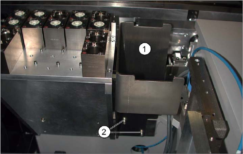
Reject bin (D1)
► If not already present, fit the "reject bin holder"
[03046974-xx] (1) with two screws "DIN912-M6x12"
[03045087-xx] (2). See also: "3.6.3 Fitting the Com-
ponent Reject Bin" [ ➙ 150]
► Insert the "reject bin for P&P head" [03041871-xx].

Installation
Installation on SX1/SX2 Machines Moving COT Insert in SX1/SX2 Machines
134 Stationary Camera Type 33/36 Stationäre Kamera Typ 33/36
3.4 Installation on SX1/SX2 Machines
Required installation kits:
See"2.3 Scope of Delivery" [ ➙ 102]
Installation kit: stationary camera type 33 for CPP head fitted in SX1/SX2 machines [00519902-xx]
The stationary camera (type 33) is already included in the HRK for TwinHead used in SX1/SX2 ma-
chines.
3.4.1 Moving COT Insert in SX1/SX2 Machines
To access the stationary camera installation position, you may need to loosen the cutter and COT insert
and push them forwards.
NOTICE
DX1/DX2
Installation of the camera in DX1/DX2 machines follows the same procedure as that used for
SX1/SX2 machines. Any differences will be mentioned explicitly.
CAUTION
Dismantling the COT insert
► Read the sections "Removing the Cutter" and "Replacing the COT Insert" in the service
manual for your machine!
NOTICE
Mark the positions of the screws
► Mark the positions of all screws, to make clear assignment easier later on.