00196608-01_AI_Stationaere_Kamera_Typ33_36_de_en.pdf - 第118页
Installation Installation on X Series and D3 Machines Electrical Connections 118 Stationary Camera Type 33/36 Stationäre Kamera Typ 33/ 36 ► Connect the black Visi on control c ables (4) and (5) to X4 or X5 "Control…
Installation
Electrical Connections Installation on X Series and D3 Machines
Stationary Camera Type 33/36 Stationäre Kamera Typ 33/36 117
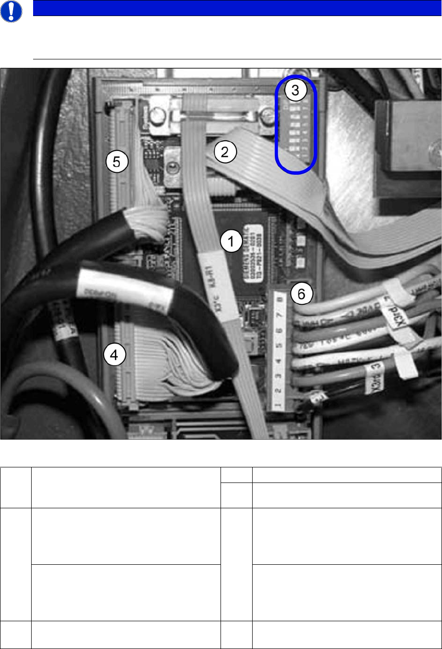
VCU with CAN bus and TQM module
► Connect the CAN bus (3) to X2.
► Connect the voltage supply cable for the "Control Unit 1 Vision, Stationary" (6).
NOTICE
BIOS and eSW version
After starting the machine, check the BIOS and Vision system application versions and, if nec-
essary, update the system with a software download.
1 TQM module [03003536-xx] on
"Control Unit 1 Vision, Stationary"
[00363961-xx]
2 CAN bus cable (X2rd)
3 DIP switch VCU
4 PA1: Subdistributor
Cable vision control IC camera 1
[03003449-xx]
To subdistributor (X4rd)
5 PA1: Subdistributor
Cable vision control FC camera 1
[03003450-xx]
To subdistributor (X5rd)
PA2: Main distributor
Cable vision control IC camera 2
[03003439-xx]
To main distributor (X4rd)
PA2: Main distributor
Cable vision control FC camera 2
[03003440-xx]
To main distributor (X5rd)
6 Cable: Voltage supply "Control Unit 1 Vi-
sion, Stationary" (X3rd)
Installation
Installation on X Series and D3 Machines Electrical Connections
118 Stationary Camera Type 33/36 Stationäre Kamera Typ 33/36
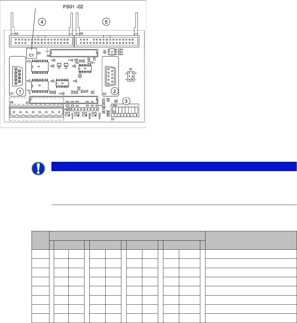
► Connect the black Vision control cables (4) and (5) to X4 or X5 "Control Unit 1 Vision, Stationary"
[00363961-xx]. See also the circuit diagrams: "4.4.1.1 Camera Up To FS02" [ ➙ 159]
Encoding of DIP switch for "Control Unit 1 Vision, Stationary" [00363961-xx]
► Set the DIP switch on the VCU (Control Unit 1 Vision, Stationary [00363961-xx]):
VCUs for X series up to number B236 with IC camera FS01 or FS02
* Not all gantries may be available, depending on the machine type.
Control Unit 1 Vision, Stationary (up to FS02)
1. X1: to TQM module
2. X2: CAN bus
3. S1: DIP switch
4. X4: Vision cable 34-pin IC camera [03003439-xx]
5. X5: Vision cable 34-pin FC camera [03003440-xx]
NOTICE
Camera configuration
When using SIPLACE X machines with stationary cameras up to FS02, you can only operate
1 gantry with stationary cameras (IC/FC) per placement area, as activation of the VCU is spe-
cific to the gantry.
S Setting for gantry* Comments
1 2 3 4
1 OFF OFF OFF OFF CAN terminator
2 OFF OFF OFF OFF Reset
3 OFF OFF OFF OFF Boot
4 OFF OFF OFF OFF CAN error switch
5ON ON OFF OFFID 1
6 ON OFF ON OFF ID 2
7 OFF OFF OFF OFF CAN speed
8 OFF OFF OFF OFF CAN group
Installation
Electrical Connections Installation on X Series and D3 Machines
Stationary Camera Type 33/36 Stationäre Kamera Typ 33/36 119
3.2.3.2 Type 33 Cameras From FS03
► Pull the three connection cables for the IC camera through the opening and out of the machine
frame.
► Check the jumper setting at the camera. For more information see section "4.2 Camera Coding and
Connections" [ ➙ 155]
► To connect the camera, read section "4.2.1 Cameras Type 33 From Version 03 To 07, Cameras
Type 36 From Version 01" [ ➙ 155].
► The connection of hotlink cards is specific to your machine. For more information, continue with the
relevant section at:
"3.2.3.3 Connecting the Hotlink Cable to the Computer Unit" [ ➙ 123] or
"3.2.3.4 Connecting the Hotlink Cable to the BoxPC" [ ➙ 124]
See also
3.5.3.1 Connecting the Hotlink Cable to the BoxPC [ ➙ 147]
3.2.3.3 Connecting the Hotlink Cable to the Computer Unit [ ➙ 123]
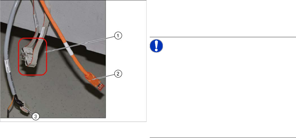
CAN bus connection (X series – from serial no. B326)
► Connect the CAN bus cable (1), the camera bus (2)
and the voltage supply (3) to the camera. For more in-
formation see section "4.4 Circuit Diagrams for X Se-
ries/D3" [ ➙ 159]
NOTICE!
Observe the FS03 and machine serial number. You may
need to install a Vision Control Unit, stationary here. The
connection of hotlink cards is also specific to the machine
used. The relevant descriptions can be found on the fol-
lowing pages of this document.
In X series machines from serial no. B160 the CAN bus
cable is looped out of the machine frame.
The CAN bus cable (03050239-xx) supplied in the retro-
fitting kit is used to connect the CAN bus cable (1) to the
camera.
► Disconnect the CAN bus cables from one another at
the coupling (1). Connect the adapter cable
[03050239-xx] in-between so that you have two addi-
tional CAN connectors available for the two stationary
cameras.