00196608-01_AI_Stationaere_Kamera_Typ33_36_de_en.pdf - 第113页
Installation Mechanical Assembly Installation on X Series and D3 Ma chines Stationary Camera Typ e 33/36 Stationäre Kamera Typ 33/36 113 3.2.2.2 Installation with Keyhole (for Camera Type 33 from Versi on 06, Type 36 fro…
Installation
Installation on X Series and D3 Machines Mechanical Assembly
112 Stationary Camera Type 33/36 Stationäre Kamera Typ 33/36
3.2.2.1 Installation with Set Screws (for Camera Type 33 up to Version 05, Type 36 up to Version 03)
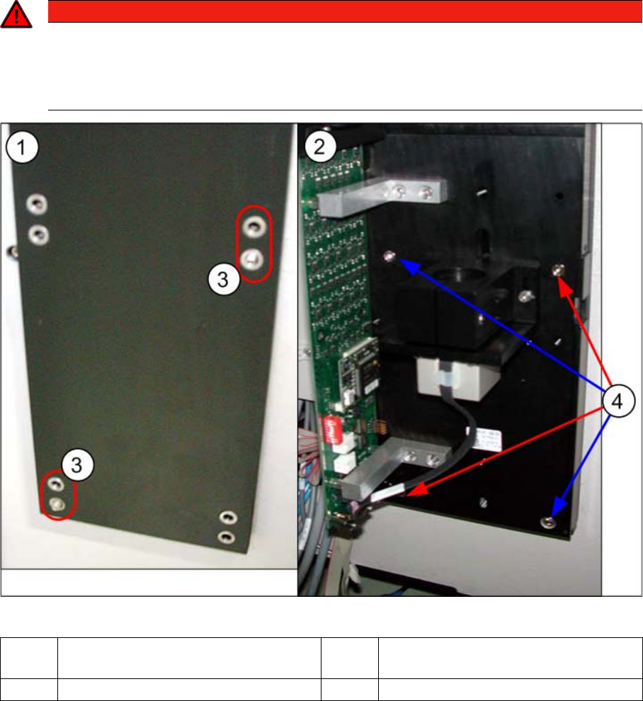
Camera in X series machine
► Screw the two set screws DIN913-M6x50-ST [03005958-xx] - with the Allen key side on the outside
- as assembly aid into the holes marked in the diagram:
Top holes: without C&P placement head
Bottom holes: with C&P placement head
► Fit the "fiducial sandwich plate" [03022077-xx] onto the set screws. Make sure that all eight holes
match the holes drilled in the machine frame. The set screws must protrude from the fiducial plate
by about 5 mm.
► Fit the camera base plate onto the "fiducial sandwich plate", so that the two set screws can be
reached. Screw the camera together with the base plate (two screws DIN912-M6x35-8.8
[00845062-xx]).
► Replace the two set screws with screws. If this is not possible, you will need to first remove the cam-
era and then move the set screws accordingly. Make sure that there is no set screw left behind the
camera as this could prevent the camera from being fitted firmly into place.
► Check the horizontal alignment of the camera with the machine spirit level.
DANGER
Sandwich plate for fiducial
The "fiducial sandwich plate" is very heavy and, when fitted, only clamped between the camera
and machine base. It can easily fall down, especially during removal.
► To prevent it falling down, proceed as follows:
1 Diagram on left: fiducial plate – on set
screws.
2 Diagram on right: camera – on fiducial
plate and set screws.
3 Set screws 4 Positions of screws
Installation
Mechanical Assembly Installation on X Series and D3 Machines
Stationary Camera Type 33/36 Stationäre Kamera Typ 33/36 113
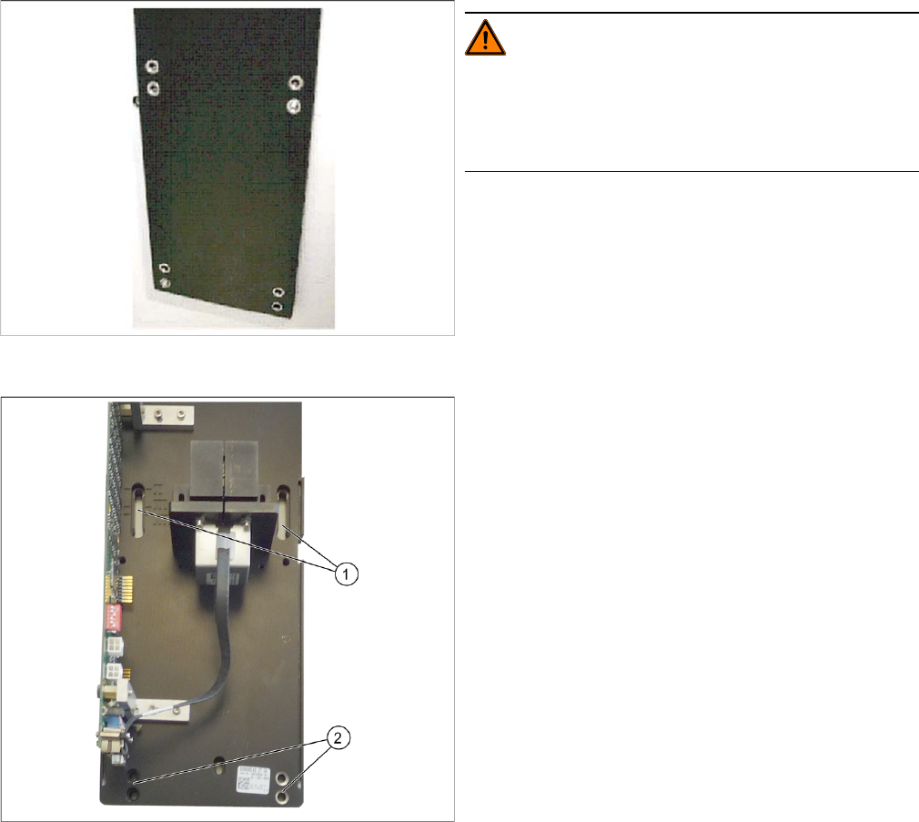
3.2.2.2 Installation with Keyhole (for Camera Type 33 from Version 06, Type 36 from Version 04)
WARNING!
Sandwich plate for fiducial
The "fiducial sandwich plate" is very heavy and, when fit-
ted, only clamped between the camera and machine
base. It can easily fall down, especially during removal.
► Fix the fiducial plate with the top two screws, so that
the plate is aligned to match the arrangement of holes
drilled in the machine. Make sure that the fiducial
plate is turned correctly (see label).
Tighten the two screws until the shaft of the screws
protrudes approx. 15 mm over the fiducial plate.
When measuring, make sure that the fiducial plate is
flush against the machine frame!
► Hook the upper holes ((1) key holes) on the lower
section of the camera onto the two screws.
► Adjust the lower section of the camera to the correct
installation height, with the two lower screws (2) and
tighten all four screws. Please also observe section
"4.1 Installation Height of the Stationary Camera"
[ ➙ 153].
► Check the horizontal alignment of the camera with
the machine spirit level.
Installation
Installation on X Series and D3 Machines Electrical Connections
114 Stationary Camera Type 33/36 Stationäre Kamera Typ 33/36
3.2.3 Electrical Connections
If you are retrofitting a TwinHead or CPP head, you can continue directly with section "3.2.3.2 Type 33
Cameras From FS03" [ ➙ 119] to fit this.
The following section describes the electrical installation for all camera versions which can be installed
in X series and D3 machines. This is also helpful for replacement of spare parts.
When retrofitting a camera using a retrofitting kit [00119782-xx], always use the latest version of the
camera (currently version 05, status 08/2011).
See also
4.2 Camera Coding and Connections [ ➙ 155]
4 Appendix [ ➙ 153]
3.2.3.1 Cameras Type 33 with FS01 or FS02 (X Series Only Up To B325)
NOTICE
Changing the machine wiring
There are differences in the component camera wiring (stationary, P&P, type 33, 55x45 digital
[03016339-xx]). One key change was made between versions FS03 and FS04. We therefore
do not recommend combining versions up until and including FS03 and from FS04 in the same
placement area and do not describe this type of combination in this manual.
NOTICE
VCU
These cameras can only be operated in conjunction with the Vision Control Unit (VCU) and in
SIPLACE X series machines with a serial number lower than B326. In these machines, the op-
eration of 4 stationary cameras or of two identical stationary cameras in one placement area is
not possible (e.g. FC/FC or IC/IC).
NOTICE
D series
The type 33 stationary camera in versions FS01 and FS02 can not be used in D series ma-
chines.
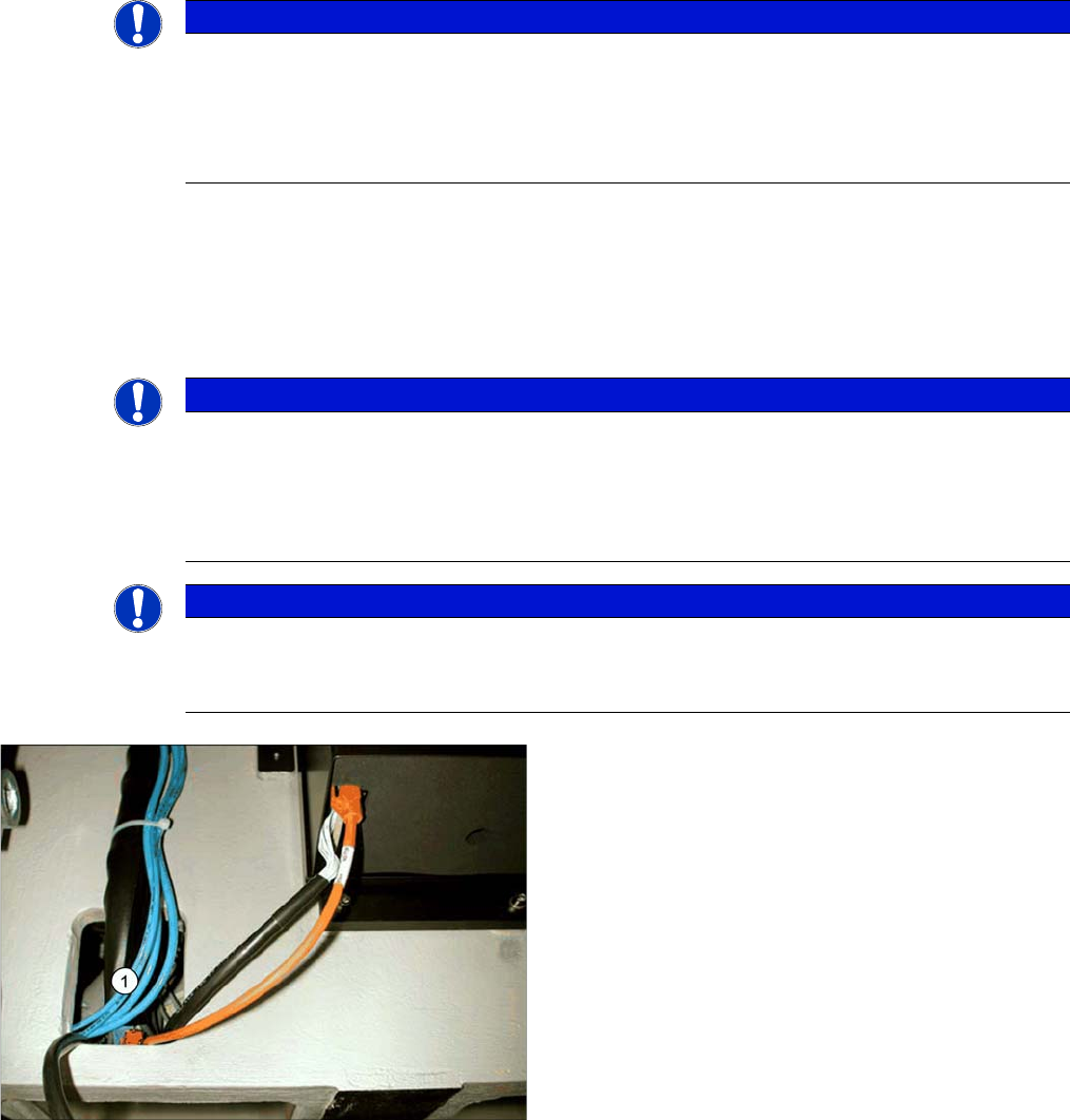
Connection cable for stationary cameras
► Pull the three connection cables for the IC camera
through the opening (1) and out of the machine
frame.