00196608-01_AI_Stationaere_Kamera_Typ33_36_de_en.pdf - 第152页
Installation General Final Work Fitting the Component Reject Bin 152 Stationary Camera Type 33/36 Stationäre Kamera Typ 33/ 36
Installation
Fitting the Component Reject Bin General Final Work
Stationary Camera Type 33/36 Stationäre Kamera Typ 33/36 151
Installation
► Fix the reject bin holder with 2 screws to the position shown on the machine frame.
► Fit the component reject bin into the holder.
3.6.3.1 Reject Bin Sensors
Note that the installation of an additional reject bin may also involve fitting sensors for the reject bin. For
more information, refer to the relevant assembly instructions.
▪ "Reject Bin Query X Series / D3, DE+EN" [00194716-xx] or
▪ "Reject Bin Query SX1/SX2, DE+EN" [00196615-xx]
The "stationary camera type 33 for CPP head in X series" [00119782-xx] contains an additional cable
with "reject bin sensors as extension kit" [03079029-xx]. In the SX series, these standard sensors are
already prepared for this configuration. Additional sensor cable are therefore not needed in this case.
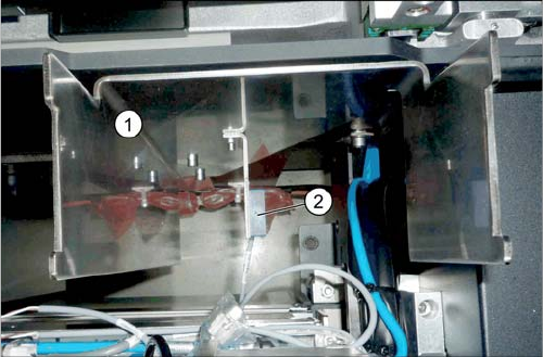
Holder for reject bins (SX1/SX2)
1. Holder for reject bins
2. Sensor for the component reject bin (optional)
Installation
General Final Work Fitting the Component Reject Bin
152 Stationary Camera Type 33/36 Stationäre Kamera Typ 33/36
Appendix
Installation Height of the Stationary Camera
Stationary Camera Type 33/36 Stationäre Kamera Typ 33/36 153
4 Appendix
4.1 Installation Height of the Stationary Camera
The installation height at which the camera can be installed depends on the camera version. You will
either only be able to use one specific height or will have the option of several installation heights. The
description below applies to the following cameras:
▪ Component camera, stationary P&P (type 33) 55x45 digital [03016339-xx] from version 06
▪ Component camera, stationary, P&P (type 36) 32 x 32, digital [03042491-xx] from version 04
CAUTION
Observe the installation height
When fitting the camera, observe the correct installation height. Othwerwise there is a risk of
head crash!
► When setting the installation height, consider all the heads in one placement area.
► If you are using a stationary camera with a CPP head, the CPP head must be fitted in the
top position.
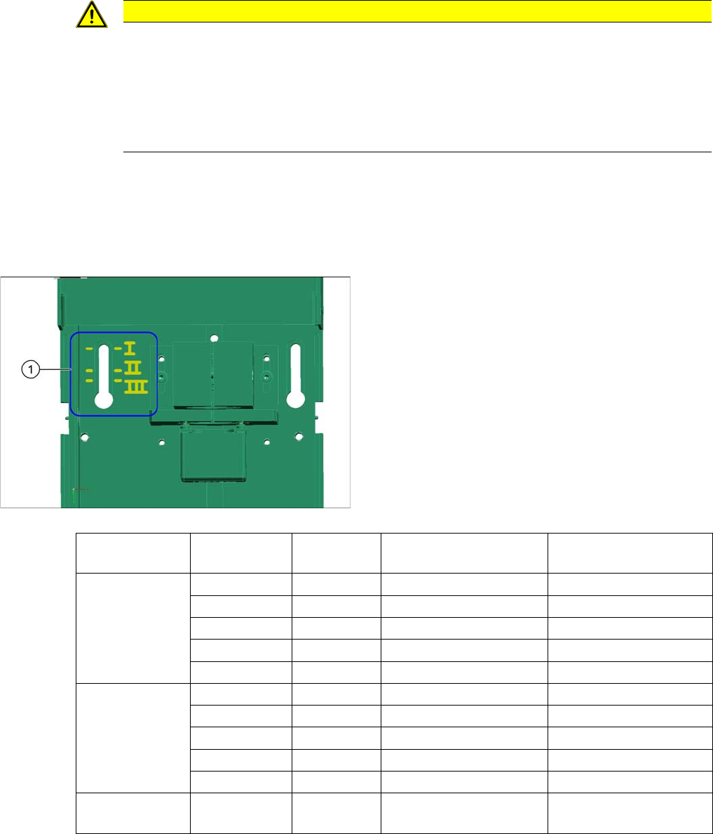
1. Installation positions I to III
Machine type Gantry A Gantry B Installation position Focal level via PCB up-
per edge
X Series DLM, CPP_H TwinHead Position I (bottom) 3.5 mm
CPP_H CPP_H Position I (bottom) 3.5 mm
TwinHead TwinHead Position III (top) 23.5 mm
CPP_H – Position I (bottom) 3.5 mm
TwinHead – Position III (top) 23.5 mm
SX series CPP_H TwinHead Position I (bottom) 12 mm
CPP_H CPP_H Position I (bottom) 12 mm
TwinHead TwinHead Position I (bottom) 12 mm
CPP_H – Position I (bottom) 12 mm
TwinHead – Position I (bottom) 12 mm
D1/D3 DLM P&P mod-
ule.
Position I (bottom) 13 mm