00196608-01_AI_Stationaere_Kamera_Typ33_36_de_en.pdf - 第107页
Installation Moving COT Insert with X Tables General Preparations Stationary Camera Typ e 33/36 Stationäre Kamera Typ 33/36 107 3.1.1 Moving COT Insert with X Tables To access the stationary camera installation position,…
Installation
General Preparations
106 Stationary Camera Type 33/36 Stationäre Kamera Typ 33/36
3.1 General Preparations
The following tasks must be performed irrespective of the machine type:
► Create a data backup file for the existing machine configuration. (Hosts.txt, MaData.zip, MaDataIn-
fo.zip, Services.txt)
► Perform a machine data backup run.
► Save the complete SRCMA folder under a different name.
► Change over to the Service menu and select "Settings --> Machine Configuration". For detailed in-
structions about how to configure the camera, refer to the Online Help.
► Configure the new camera (standard camera type 33) in the machine configurator and save the data.
► Remove the component trolley/WPC from the camera installation position.
► Switch off the machine and secure it to prevent unauthorized reactivation. Observe the instructions
in section "1.2 Preparatory Work..." [ ➙ 93].
► Remove the waste tape chute. This is either screwed or hooked into place, depending on your ma-
chine.
► Change the machine configuration for the new camera in SIPLACE Pro.
► Perform placement program optimization for the line.
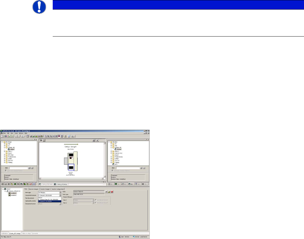
Configuration of stationary camera with SIPLACE Pro
See also
1.2 Preparatory Work... [ ➙ 93]
NOTICE
Camera configuration
For detailed instructions about how to configure the camera, refer to the SITEST Online Help
at "Settings - Settings for Placement Head".
Configuration of stationary camera (using example of D1)
► Switch over to "Setup-Location-Head tab" and enter
the P&P head.
► Re-optimize the setup in SIPLACE Pro.
Installation
Moving COT Insert with X Tables General Preparations
Stationary Camera Type 33/36 Stationäre Kamera Typ 33/36 107
3.1.1 Moving COT Insert with X Tables
To access the stationary camera installation position, you may need to loosen the COT insert and push
it forwards.
3.1.1.1 Overview
3.1.1.2 Dismantling the Side Cover (X Series and D3)
CAUTION
Service manual
► Read the section "Replacing the COT Insert" in your service manual!
NOTICE
Example of X series
The following description of how to move the COT insert uses the example of an X series ma-
chine, unless it states otherwise. The procedure is the same for other machines.
NOTICE
Mark the positions of the screws
► Mark the positions of all screws, to make clear assignment easier later on.
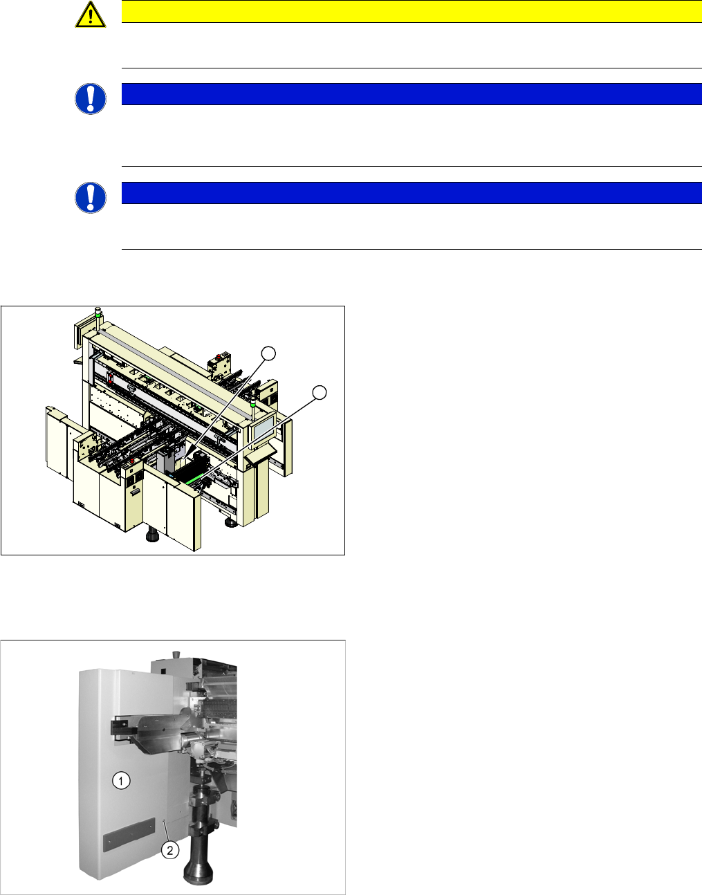
COT insert (using example of X series)
1. COT insert assembly
2. Installation position for stationary cameras
1
2
► Undock the component trolley from the placement
machine at the installation position of the stationary
camera.
► Switch the placement machine off at the main switch.
► Loosen the screw (2), fastening the side cover (1) on
the inside.
Installation
General Preparations Moving COT Insert with X Tables
108 Stationary Camera Type 33/36 Stationäre Kamera Typ 33/36
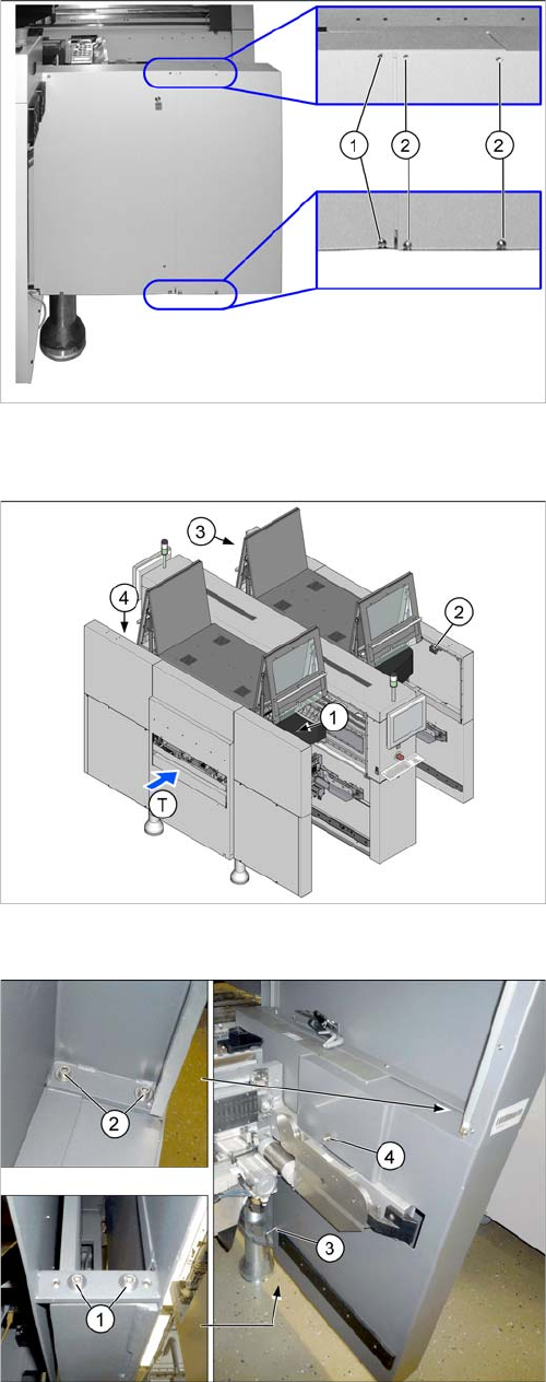
3.1.1.3 Dismantling the Lower Side Cover (SX4)
► Loosen the two screws (1), in order to pull out the side
cover.
► Loosen the four screws (2) fastening the side cover
and remove these. Hold the side cover while you are
removing the screws.
Position of protective switches on the placement machine
1. Protective cover switch, location 1
2. Protective cover switch, location 2
3. Protective cover switch, location 3
4. Protective cover switch, location 4
T = PCB direction of transport
► To do this, loosen the 6 screws fastening the side
cover in the order (1) to (4) and remove these. While
unscrewing, always hold on to the side cover, to pre-
vent it falling off.