00196608-01_AI_Stationaere_Kamera_Typ33_36_de_en.pdf - 第117页
Installation Electrical Connections Installation on X Series and D3 Machines Stationary Camera Typ e 33/36 Stationäre Kamera Typ 33/36 117 VCU with CAN bu s and TQM module ► Connect the CAN bus (3) to X2. ► Connect the v…
Installation
Installation on X Series and D3 Machines Electrical Connections
116 Stationary Camera Type 33/36 Stationäre Kamera Typ 33/36
Connection to the Vision Control Unit Stationary Up To Serial Number B325 and IC Camera FS01 and
FS02
NOTICE
Observe the machine serial number and camera FS number.
Observe this section for X series machines up to serial number B325 and IC cameras with FS01
or FS02.
NOTICE
CPP and VCU
The Vision Control Unit (VCU) does not support CPP heads. CPP heads and the corresponding
stationary cameras are therefore only possible from machine serial number B326.
► In this case, read the corresponding assembly instructions for information about further re-
strictions.
NOTICE
TQM module
The TQM module [03003536-xx] is not part of the camera delivery package and will need to be
ordered separately if required.
NOTICE
Control Unit 1 Vision, Stationary [00363961-xx]
The "Control Unit 1 Vision, Stationary" [00363961-xx] is part of the "Reconfig. parts kit parts kit
for X series/TwinHead" [03041487-xx].
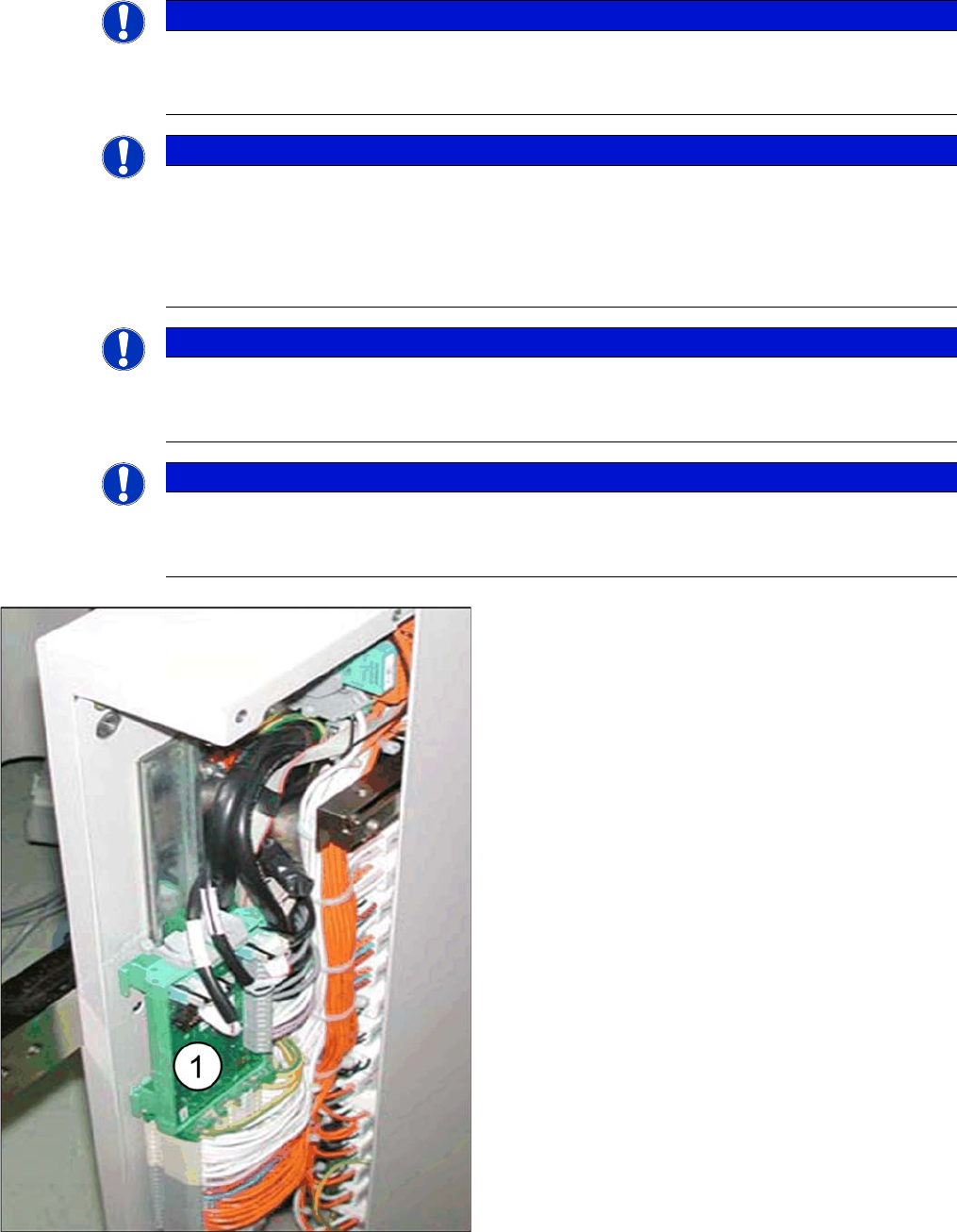
VCU
► Connect the TQM module to the "Control Unit 1 Vi-
sion, Stationary" [00363961-xx] board.
► Fit the "Control Unit 1 Vision, Stationary" [00363961-
xx] with the connected "TQM167 SIPLACE embed-
ded module" [03003536-xx] in the relevant slot (1).
▪ The VCU for PA1 is located in the subdistributor (lo-
cation 4).
▪ The VCU for PA2 is located in the main distributor (lo-
cation 2).
Installation
Electrical Connections Installation on X Series and D3 Machines
Stationary Camera Type 33/36 Stationäre Kamera Typ 33/36 117
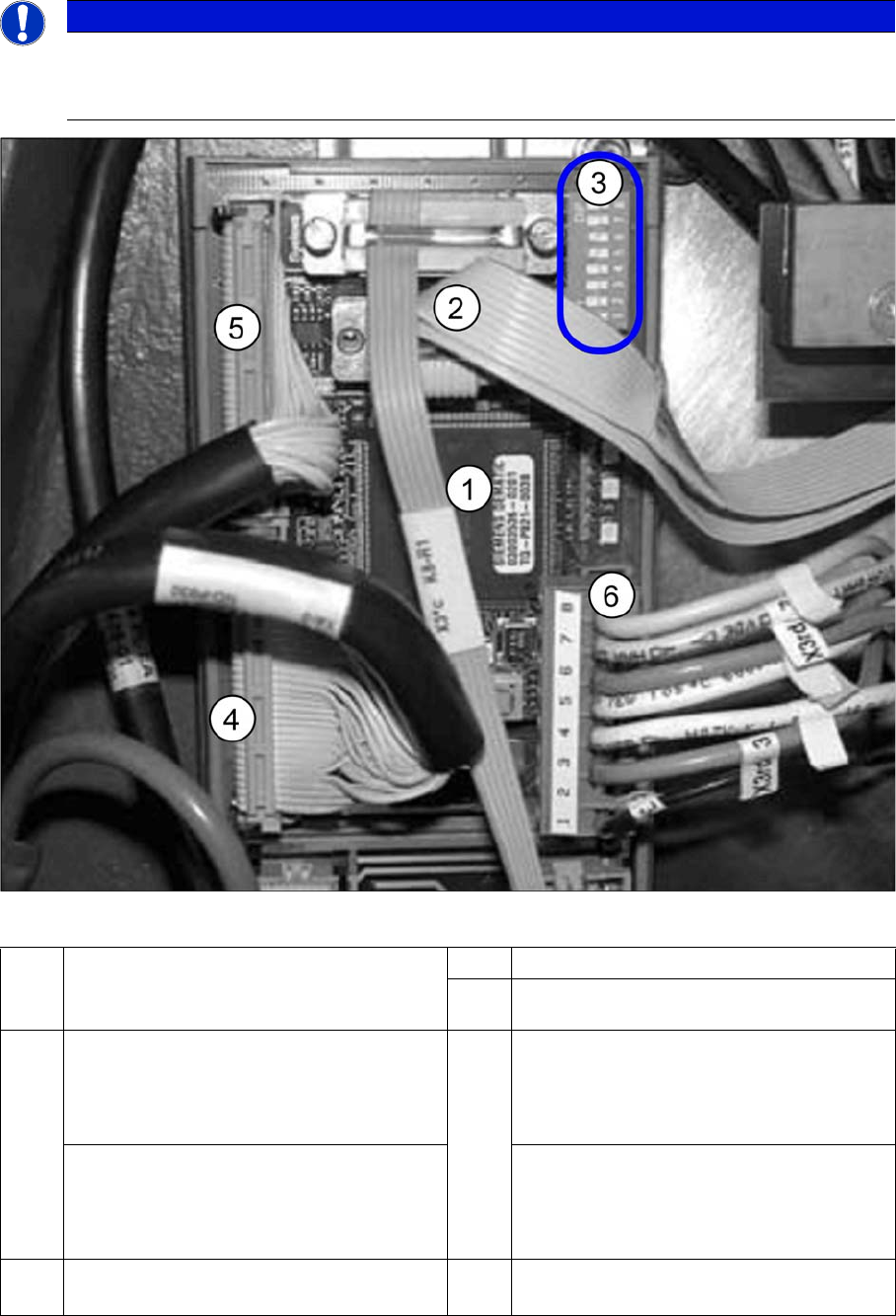
VCU with CAN bus and TQM module
► Connect the CAN bus (3) to X2.
► Connect the voltage supply cable for the "Control Unit 1 Vision, Stationary" (6).
NOTICE
BIOS and eSW version
After starting the machine, check the BIOS and Vision system application versions and, if nec-
essary, update the system with a software download.
1 TQM module [03003536-xx] on
"Control Unit 1 Vision, Stationary"
[00363961-xx]
2 CAN bus cable (X2rd)
3 DIP switch VCU
4 PA1: Subdistributor
Cable vision control IC camera 1
[03003449-xx]
To subdistributor (X4rd)
5 PA1: Subdistributor
Cable vision control FC camera 1
[03003450-xx]
To subdistributor (X5rd)
PA2: Main distributor
Cable vision control IC camera 2
[03003439-xx]
To main distributor (X4rd)
PA2: Main distributor
Cable vision control FC camera 2
[03003440-xx]
To main distributor (X5rd)
6 Cable: Voltage supply "Control Unit 1 Vi-
sion, Stationary" (X3rd)
Installation
Installation on X Series and D3 Machines Electrical Connections
118 Stationary Camera Type 33/36 Stationäre Kamera Typ 33/36
► Connect the black Vision control cables (4) and (5) to X4 or X5 "Control Unit 1 Vision, Stationary"
[00363961-xx]. See also the circuit diagrams: "4.4.1.1 Camera Up To FS02" [ ➙ 159]
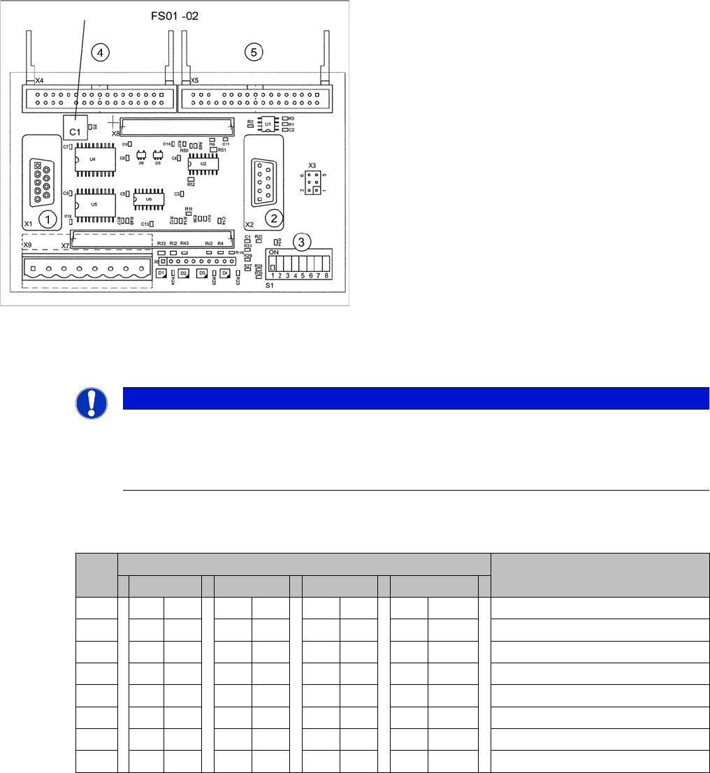
Encoding of DIP switch for "Control Unit 1 Vision, Stationary" [00363961-xx]
► Set the DIP switch on the VCU (Control Unit 1 Vision, Stationary [00363961-xx]):
VCUs for X series up to number B236 with IC camera FS01 or FS02
* Not all gantries may be available, depending on the machine type.
Control Unit 1 Vision, Stationary (up to FS02)
1. X1: to TQM module
2. X2: CAN bus
3. S1: DIP switch
4. X4: Vision cable 34-pin IC camera [03003439-xx]
5. X5: Vision cable 34-pin FC camera [03003440-xx]
NOTICE
Camera configuration
When using SIPLACE X machines with stationary cameras up to FS02, you can only operate
1 gantry with stationary cameras (IC/FC) per placement area, as activation of the VCU is spe-
cific to the gantry.
S Setting for gantry* Comments
1 2 3 4
1 OFF OFF OFF OFF CAN terminator
2 OFF OFF OFF OFF Reset
3 OFF OFF OFF OFF Boot
4 OFF OFF OFF OFF CAN error switch
5ON ON OFF OFFID 1
6 ON OFF ON OFF ID 2
7 OFF OFF OFF OFF CAN speed
8 OFF OFF OFF OFF CAN group