00196608-01_AI_Stationaere_Kamera_Typ33_36_de_en.pdf - 第99页
Brief Description Product Description Stationary Camera Typ e 33/36 Stationäre Kamera Typ 33/36 99 2 Brief Description 2.1 Product Description Installation position Camera struc ture 1. Station ary camera, type 33/36 (IC…

Introduction
Abbreviations SIPLACE on the World Wide Web (WWW)
98 Stationary Camera Type 33/36 Stationäre Kamera Typ 33/36
1.5 Abbreviations
Abbreviations Description
PA, PA1, PA2 Placement area, Placement area 1, Placement area 2
CO Component
COT Changeover table
COT-i Changeover table insert
C&P Collect&Place
C&P12, CP12 Collect&Place head with 12 segments
C&P20, CP20 Collect&Place head with 20 segments
C&P6, CP6 Collect&Place head with 6 segments
CPP Collect&Pick&Place head
CPx Collective term for CPP, CP20, CP12 and/or CP6
ESD Electrostatic sensitive device
EMC Electromagnetic compatibility
FS Function status, version
HRK Head reconfiguration kit
PCB Board
P&P Pick&Place
TH TwinHead
VCU Vision Control Unit, also: Control Unit Vision Stationary
WPC Wafflepack Changer
WPC4/5/6 Wafflepack Changer Version 4/5/6
Brief Description
Product Description
Stationary Camera Type 33/36 Stationäre Kamera Typ 33/36 99
2 Brief Description
2.1 Product Description
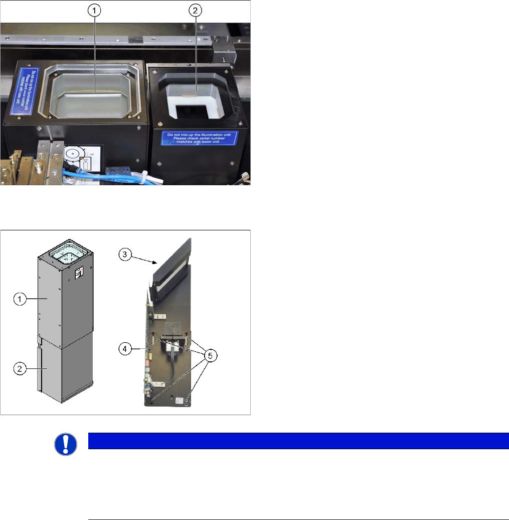
Installation position
Camera structure
1. Stationary camera, type 33/36 (IC camera)
2. Stationary camera, type 25 (FC camera)
Component camera, stationary P&P (type 33) 55x45
Component camera, stationary P&P (type 36) 32x32 dig-
ital
1. Upper section of camera (illumination unit)
2. Lower section of camera
3. Glass sheet
4. Camera electronics
5. Holes for fastening screws
NOTICE
The upper section of the camera is assigned specifically to the lower section of the camera!
The upper section of the camera may not be used with a different bottom section. Both the up-
per and lower sections are mechanically and electrically coordinated and may not be ex-
changed for use with other cameras. The serial and version numbers of the top and bottom
sections of the camera must be identical.

Brief Description
Product Description Technical Data.
100 Stationary Camera Type 33/36 Stationäre Kamera Typ 33/36
2.1.1 Technical Data.
2.1.1.1 Component Camera, Stationary, P&P (Type 33) 55x45
The "component camera stationary P&P (type 33) 55x45" provides a resolution of 41 µm and a wider
available component spectrum of up to 55x45 mm. This stationary camera can, for example, be ordered
if you require greater resolution or when you need to place multiple components which are larger than
the field of view supported by your standard camera. For more information about this data, refer to the
specification documents for the relevant placement head or for the standard camera.
2.1.1.2 Component Camera, Stationary, P&P (Type 36) 32x32
The placement accuracy of the "component camera stationary P&P (type 36) 32x32" is specific to the
machine and head used. For more information about this data, refer to the specification documents for
the relevant placement head or for the standard camera.
2.1.2 Version Overview
Component dimensions 0.5 mm x 0.5 mm up to 55 mm x 45 mm
Component spectrum 0402, MELF, SO, PLCC, QFP, electrolytic capaci-
tors, BGA
Min. lead pitch 0.30 mm
Min. lead width 0.15 mm
Min. ball pitch 0.35 mm
Min. ball diameter 0.20 mm
Field of view
65x50 mm
2
Method of illumination Front-lighting (6 levels, programmable as re-
quired)
Component dimensions 0.8 x 0.8 mm イ to 32 x 32 mm イ (simple measure-
ment)
Component spectrum 0603, MELF, SO, PLCC, QFP, electrolytic capaci-
tors, BGA
Min. lead pitch 0.40 mm
Min. lead width 0.24 mm
Min. ball pitch 0.56 mm
Min. ball diameter 0.32 mm
Field of view
38x38 mm
2
Method of illumination Front-lighting (6 levels, programmable as re-
quired)
Version
SST33
Version
SST36
Description
01, 02 --- Without CAN controller, VCU required (CAN and power supply via VCU)
03 to 06 01 With CAN controller (as TQ module), VCU not required, 8 pin DIP switch on the
driver board
From 06 From 04 Simpler assembly with key holes
From 07 From 05 With CAN controller (integrated on the board), VCU not required, 6 pin DIP switch
on the driver board