00196608-01_AI_Stationaere_Kamera_Typ33_36_de_en.pdf - 第156页
Appendix Camera Coding and Connections Cameras Type 33 From Version 03 To 07, Camer as Type 36 From Version 01 156 Stationary Camera Type 33/36 Stationäre Kamera Typ 33/ 36 Vision LED driver board VLT33 from FS03 1 X 3: …
Appendix
Cameras Type 33 From Version 03 To 07, Cameras Type 36 From Version 01 Camera Coding and Connections
Stationary Camera Type 33/36 Stationäre Kamera Typ 33/36 155
4.2 Camera Coding and Connections
See also
2.1.2 Version Overview [ ➙ 100]
4.2.1 Cameras Type 33 From Version 03 To 07, Cameras Type 36 From Version 01
General
In these cameras, the CAN controller is located directly on the driver board. However, this camera can
also be operated on the VCU. The connection is realized via the CAN bus for machines with a serial
number from approx. B326. The connection is still possible via the VCU for machines with a serial num-
ber below B326.
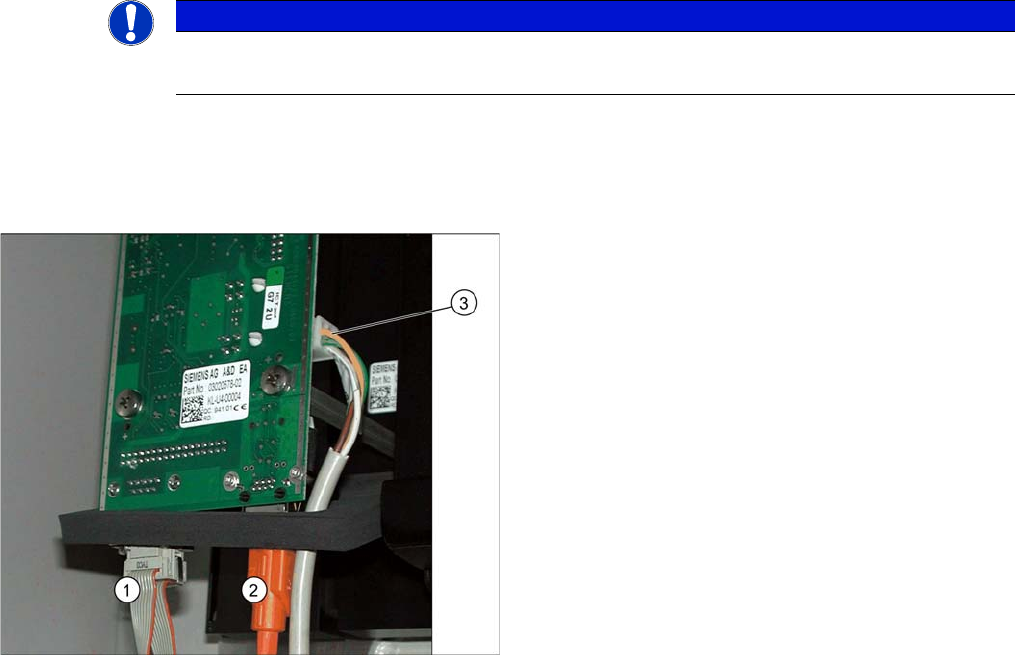
4.2.1.1 Camera Connection Board VLT33
For independent operation (not via the VCU), the camera cable, the CAN bus cable and the power sup-
ply are connected directly.
NOTICE
Coding the DIP switch
Newer cameras (type 33 from version 07, type 36 from version 05) have a 6-pin DIP switch.
1. CAN bus
2. Camera cable (hotlink cable)
3. Cable for power supply
Appendix
Camera Coding and Connections Cameras Type 33 From Version 03 To 07, Cameras Type 36 From Version 01
156 Stationary Camera Type 33/36 Stationäre Kamera Typ 33/36
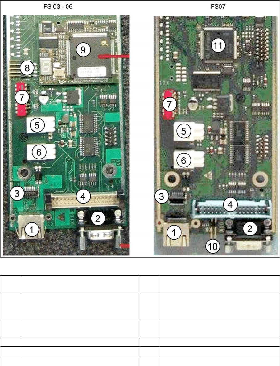
Vision LED driver board VLT33 from FS03
1 X3: Camera bus to station computer hotlink
card
2CAN bus
3 Not relevant 4 Vision cable 34-pin IC camera [03003439-
xx] to Vision controller
For machines up to serial number B326
5 X4: Cable for power supply 6 X5: Cable for power supply
Bridge to FC camera
7 DIP switch 8 Not relevant
9 Controller plug-in card FS03 to FS06 10 Not relevant
11 Controller onboard from FS07
Appendix
Cameras Type 33 From Version 03 To 07, Cameras Type 36 From Version 01 Camera Coding and Connections
Stationary Camera Type 33/36 Stationäre Kamera Typ 33/36 157
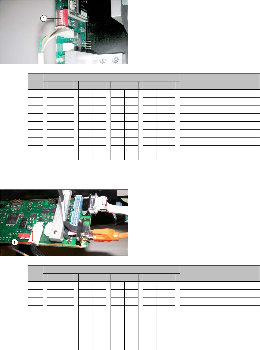
4.2.1.2 Coding the DIP Switch (8 Pin)
* Not all gantries may be available, depending on the machine type.
4.2.1.3 Coding the DIP Switch (6 Pin)
* Not all gantries may be available, depending on the machine type.
► Set the DIP switch (1) on the camera.
S Setting for gantry* Comments
1 2 3 4
1 OFF OFF OFF OFF Boot
2 OFF OFF OFF OFF Reset
3 OFF ON OFF ON Gantry ID 0
4OFFOFFONON Gantry ID 1
5 OFF OFF OFF OFF Test
6 OFF OFF OFF OFF CAN terminator
7ON ON ON ON 1 Mbit/s
8 xx xx xx x x x = OFF: FC camera (type 25)
x = ON: IC camera (type 33/36)
► Set the DIP switch (1) on the camera.
S Setting for gantry* Comments
1 2 3 4
1 OFF OFF OFF OFF Reset
2 OFF ON OFF ON Gantry ID 0
3OFFOFFONON Gantry ID 1
4 x x x x x x x x LED: This switch is delivered with
a fixed presetting. Do not change
this setting!
5 OFF OFF OFF OFF CAN terminator
6 x x x x x x x x x = OFF: FC camera (type 25)
x = ON: IC camera (type 33/36)