00196608-01_AI_Stationaere_Kamera_Typ33_36_de_en.pdf - 第124页
Installation Installation on X Series and D3 Machines Electrical Connections 124 Stationary Camera Type 33/36 Stationäre Kamera Typ 33/ 36 3.2.3.4 Connecting the Hotlink Cable to the BoxPC In the SIPLACE X4, two types of…
Installation
Electrical Connections Installation on X Series and D3 Machines
Stationary Camera Type 33/36 Stationäre Kamera Typ 33/36 123
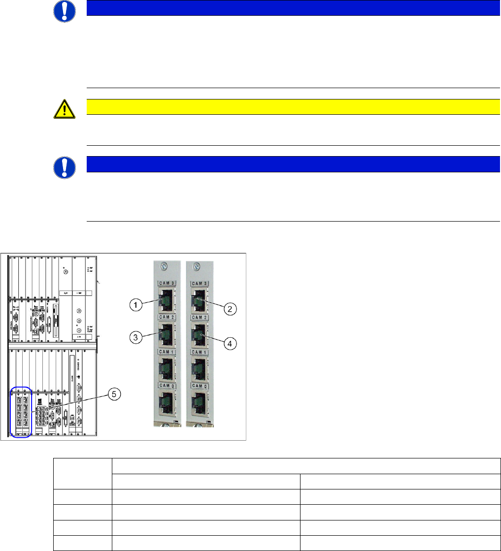
3.2.3.3 Connecting the Hotlink Cable to the Computer Unit
► Connect your camera cable to the hotlink cards as follows:
NOTICE
Observe the machine serial number
Observe this section for X series and D3 machines up to serial number B325. These machines
were supplied with a computer unit.
An exception to this are X series machines which have been upgraded to CPP with SW70x. In
these machines the computer unit has been replaced with a box PC.
CAUTION
Never connect a LAN cable to the hotlink card
This could damage the hotlink card.
NOTICE
Connection for stationary cameras
► Observe section "4 Appendix" [ ➙ 153] and the latest circuit diagrams for your machine.
► The camera cables are labeled with their relevant connection details.
Hotlink cards to the computer unit
1. FC camera for PA1 CAM3 (X3pr)
2. FC camera for PA2 CAM3 (X3ps)
3. IC camera for PA1 CAM2 (X2pr)
4. IC camera for PA2 CAM2 (X2ps)
5. Hotlink cards
To (5) hotlink cards
PA1 - card 1 (left) PA2 - card 2 (right)
CAM0 Gantry 1: PCB/component camera Gantry 2: PCB/component camera
CAM1 Gantry 4: PCB/component camera Gantry 3: PCB/component camera
CAM2 (3) IC camera PA1 → cable X2pr (4) IC camera PA2 → cable X2ps
CAM3 (1) Gantry 4 FC camera → cable X3pr (2) Gantry 3 FC camera → cable X3ps
Installation
Installation on X Series and D3 Machines Electrical Connections
124 Stationary Camera Type 33/36 Stationäre Kamera Typ 33/36
3.2.3.4 Connecting the Hotlink Cable to the BoxPC
In the SIPLACE X4, two types of hotlink cards can be fitted. When installed, these can only be differen-
tiated from the PCI-A14 by looking at the order of camera input connections. See the following diagrams
for an illustration of this.
► Connect your camera cable as follows:
NOTICE
Observe the machine serial number
Observe this section for X series machines from serial number B326. These machines were
delivered with a box PC.
In addition, this applies to X series machines up to serial number B325 which have been up-
graded to CPP with SW70x. In these machines the computer unit has been replaced with a box
PC.
CAUTION
Never connect a LAN cable to the hotlink card!
This could damage the hotlink card.
NOTICE
Connection for stationary cameras
► Observe section "4 Appendix" [ ➙ 153] and the latest circuit diagrams for your machine.
► When installed, the version of your hotlink card can only be determined by the position of
the camera connection label and the order of CAM connections.
► The stationary cameras are always connected to CAM2 or CAM3.
► The camera cables are labeled with their relevant connection details according to the pat-
tern X*p*.
CAUTION
Correctly connecting the camera cable
► Make sure that you connect the cameras correctly. Observe the labels on the hotlink cards
and therefore the type of hotlink card used. If you do not observe this, placement perfor-
mance may be adversely affected.
Pay particular attention to the different order of connections on the PCI-A24!
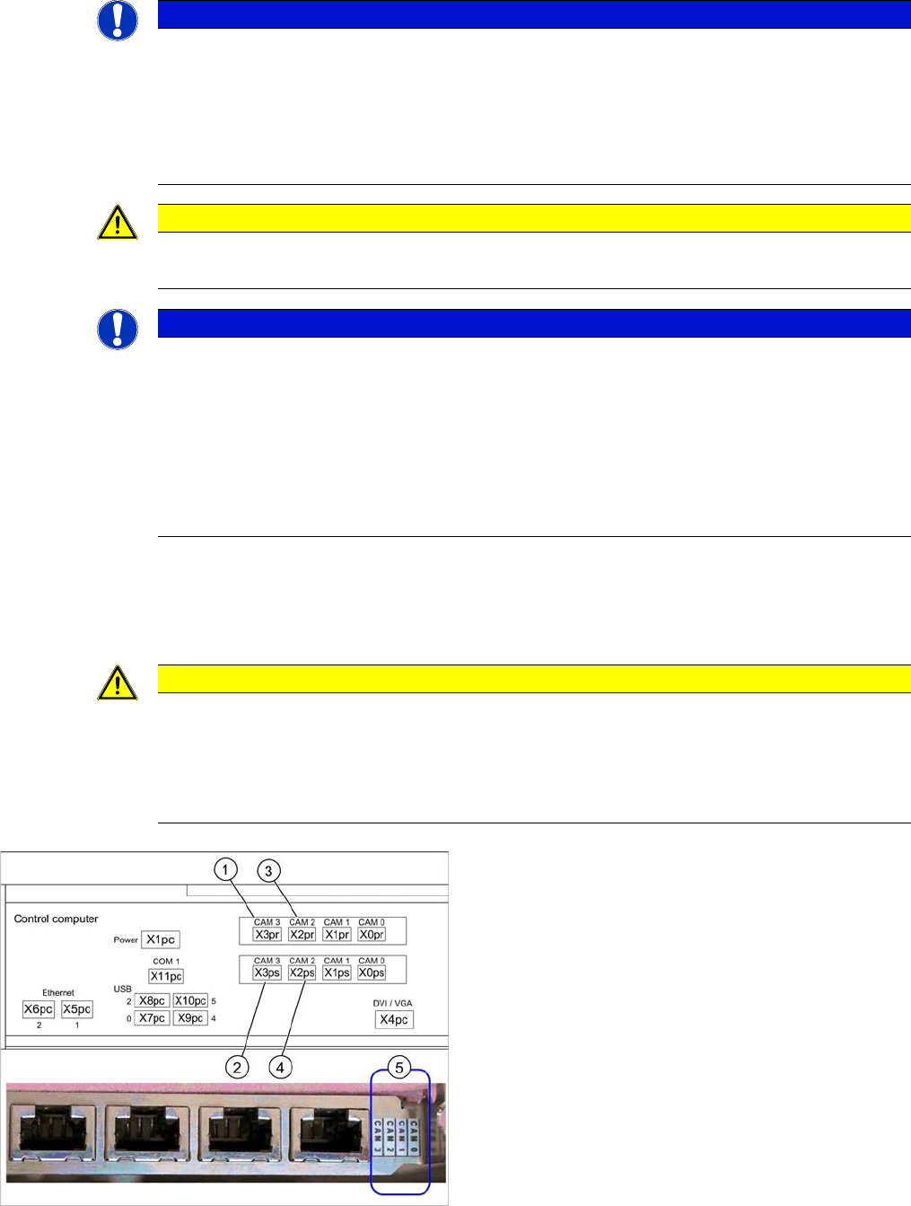
Hotlink card (PCI-A14 [03032343-xx])
The hotlink card is installed as a default with the box PC
627 up to approx. machine serial number B1125.
When installed, the version of the hotlink cards can only
be seen on the label for the camera connections (5).
(1) and (3): Stationary cameras for placement area 1
(X2pr and X3pr)
(2) and (4): Stationary cameras for placement area 2
(X2ps and X3ps)
Installation
Electrical Connections Installation on X Series and D3 Machines
Stationary Camera Type 33/36 Stationäre Kamera Typ 33/36 125
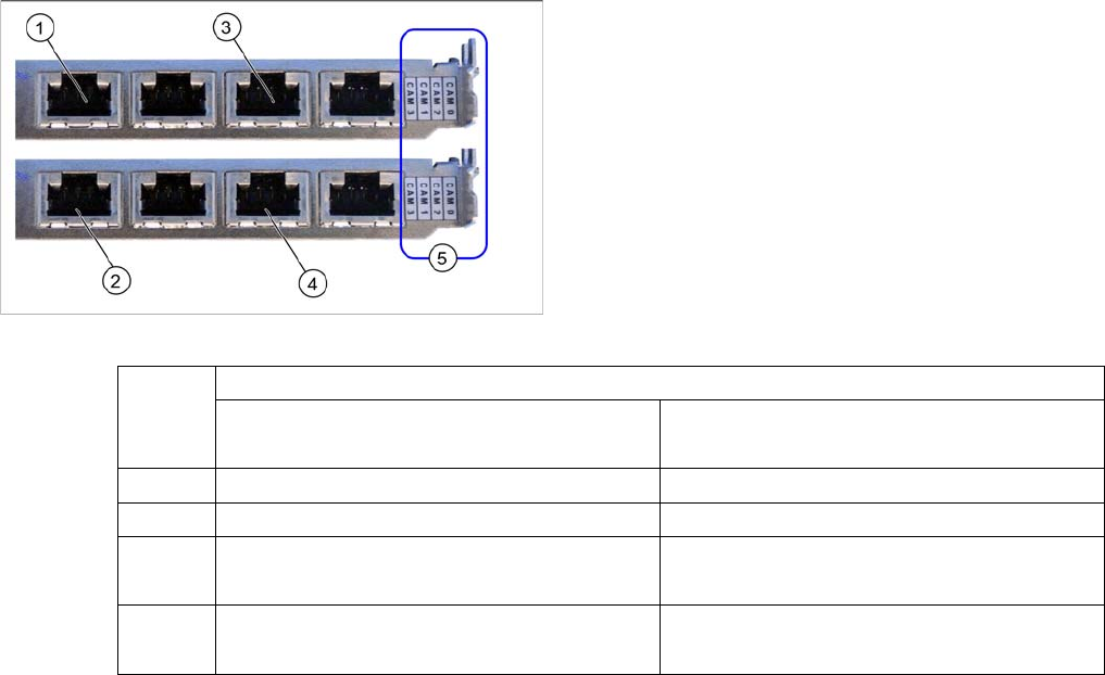
Hotlink card (PCI-A24 [03052135-xx])
The hotlink card is installed as a default with the box PC
627B up to approx. machine serial number B1125. in
principle, the use of a hotlink card is possible from
SW605.03 (e.g. as spare part).
When installed, the version of the hotlink cards can only
be seen on the label for the camera connections (5).
(1) and (3): Stationary cameras for placement area 1
(X2pr and X3pr)
(2) and (4): Stationary cameras for placement area 2
(X2ps and X3ps)
Hotlink cards
PA1
Card 1 (top)
PA2
Card 2 (bottom)
CAM0 Gantry 1 - PCB/component camera Gantry 2 - PCB/component camera
CAM1 Gantry 4 - PCB/component camera Gantry 3 - PCB/component camera
CAM2 Gantry 1 - stationary cameras (IC/FC)
→ Cable X2pr
Gantry 2 - stationary cameras (IC/FC)
→ Cable X2ps
CAM3 Gantry 4 - stationary cameras (IC/FC)
→ Cable X3pr
Gantry 3 - stationary cameras (IC/FC)
→ Cable X3ps