00196608-01_AI_Stationaere_Kamera_Typ33_36_de_en.pdf - 第143页
Installation Final Wo rk Installation on SX1/SX2 Machines Stationary Camera Typ e 33/36 Stationäre Kamera Typ 33/36 143 3.4.5 Final Work ► Fit the camera hou sing. See a lso" 3.6.1 Assembling the Camera" [➙ 1 …
Installation
Installation on SX1/SX2 Machines Electrical Connections
142 Stationary Camera Type 33/36 Stationäre Kamera Typ 33/36
3.4.4.1 Connecting the Hotlink Cable to the BoxPC
Two types of hotlink cards can be fitted in SX1/SX2 machines. When installed, these can only be differ-
entiated by looking at the order of camera input connections. See the following diagrams for an illustra-
tion of this.
► Connect your camera cable as follows:
CAUTION
Never connect a LAN cable to the hotlink card!
This could damage the hotlink card.
NOTICE
Connection for stationary cameras
► Observe section "4 Appendix" [ ➙ 153] and the latest circuit diagrams for your machine.
► When installed, the version of your hotlink card can only be determined by the position of
the camera connection label and the order of CAM connections.
► The stationary cameras are always connected to CAM2 or CAM3.
► The camera cables are labeled with their relevant connection details according to the pat-
tern X*p*.
CAUTION
Correctly connecting the camera cable
► Make sure that you connect the cameras correctly. Observe the labels on the hotlink cards
and therefore the type of hotlink card used. If you do not observe this, placement perfor-
mance may be adversely affected.
Pay particular attention to the different order of connections on the PCI-A24!
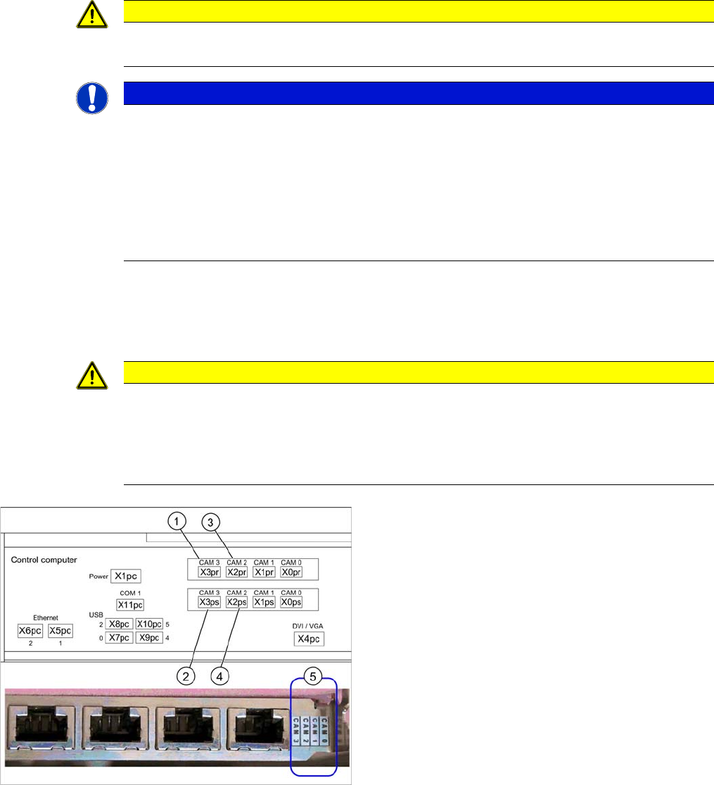
Hotlink card (PCI-A14 [03032343-xx])
This hotlink card is installed as a default in SX1/SX2 ma-
chines up to approx. machine serial number K200G.
When installed, the version of the hotlink cards can only
be seen on the label for the camera connections (5).
(1) and (3): Stationary cameras for placement area 1
(X2pr and X3pr)
(2) and (4): Stationary cameras for placement area 2
(X2ps and X3ps)
Installation
Final Work Installation on SX1/SX2 Machines
Stationary Camera Type 33/36 Stationäre Kamera Typ 33/36 143
3.4.5 Final Work
► Fit the camera housing. See also"3.6.1 Assembling the Camera" [➙149]
► Fit the COT insert if necessary. Read the service manual for your machine first.
► Hook the waste tape chute back into place.
► Fit the "reject bin holder" [03063283-xx] with two DIN912-M6x12 screws [03045087-xx]. See al-
so"3.6.3 Fitting the Component Reject Bin" [ ➙ 150]
► If the reject bin sensor is present, you will need to fit this in a new position for the SX series machine.
For more information, refer to the assembly instructions "Reject Bin Query SX1/SX2, DE+EN"
[00196615-xx].
► Insert the "reject bin for TwinHead" [03072806-xx].
► Make sure that there are no objects in the travel area of the gantry and remove any which are.
► Start the machine and move the component trolley back into the machine.
► Calibrate the machine. See also"3.6.2 Calibrating the Camera" [➙150]
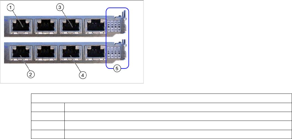
Hotlink card (PCI-A24 [03052135-xx])
This hotlink card is installed as a default in SX1/SX2 ma-
chines from approx. machine serial number K200G and
in DX1/DX2 machines.
When installed, the version of the hotlink cards can only
be seen on the label for the camera connections (5).
(1) and (3): Stationary cameras for placement area 1
(X2pr and X3pr)
(2) and (4): Stationary cameras for placement area 2
(X2ps and X3ps)
Hotlink card
CAM0 Gantry 1 - PCB/component camera
CAM1 Gantry 2 - PCB/component camera
CAM2 Gantry 1 - stationary cameras (IC/FC) → cable X2pr
CAM3 Gantry 2 - stationary cameras (IC/FC) → cable X3pr
Installation
Installation on SX4 Machines Installation position for SX4 Machines
144 Stationary Camera Type 33/36 Stationäre Kamera Typ 33/36
3.5 Installation on SX4 Machines
Required installation kits:
See"2.3 Scope of Delivery" [ ➙ 102]
Installation kit: stationary camera type 33 an SX4 [00519828-xx]
The stationary camera (type 33) is already included in the HRK for TwinHead used in SX4 machines.
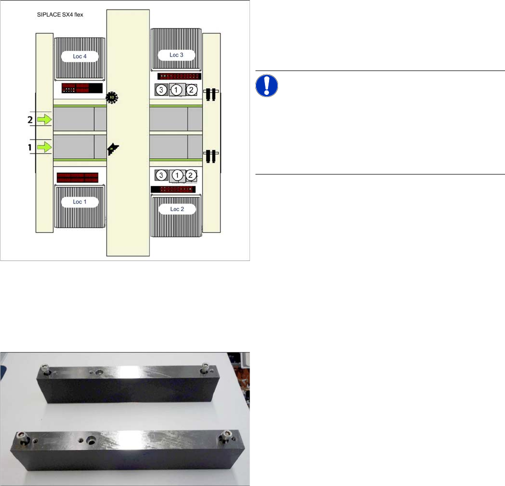
3.5.1 Installation position for SX4 Machines
3.5.2 Mechanical Assembly
Fitting the mounts
Installation position of cameras (SX4 flex)
1. IC camera, type 33
2. FC camera/3D coplan
3. Component reject bin
Loc 1 to Loc 4: location 1 to 4
NOTICE!
TwinHead
The FC camera and the 3D coplan module are only pos-
sible together with a TwinHead. Only one of these options
can be fitted at the same location, meaning that either the
FC camera or the 3D coplan module can be used.
Mounts for stationary cameras (SX4)
If not already present, you will need to fit the mounts for
the stationary cameras. Proceed as follows: