00196608-01_AI_Stationaere_Kamera_Typ33_36_de_en.pdf - 第131页
Installation Electrical Connections Assembly in a D1 Machine Stationary Camera Typ e 33/36 Stationäre Kamera Typ 33/36 131 3.3.3 Electrical Co nnections See also 4. 2.1 Camera s Type 33 From Versio n 03 To 07, Camera…
Installation
Assembly in a D1 Machine Mechanical Assembly
130 Stationary Camera Type 33/36 Stationäre Kamera Typ 33/36
► Fit the camera base unit onto the set screws and fasten this base unit, together with the fiducial sand-
wich plate, using two socket head screws (Allen screws) DIN912-M6x35-8.8 [00845062-xx].
► Replace the two set screws with two socket head screws (Allen screws) DIN912-M6x35-8.8
[00845062-xx]. Screw the camera tight.
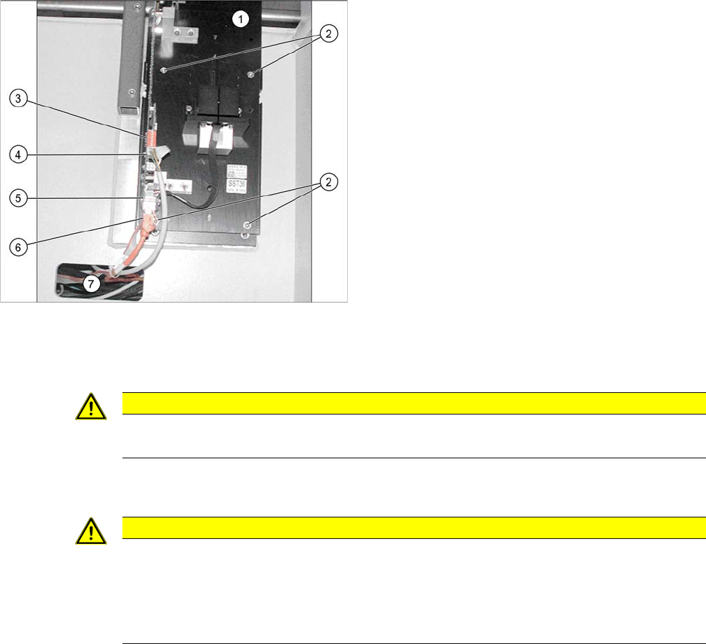
Stationary camera - camera base plate (D1)
1. Stationary camera
2. Screws DIN912-M6x35-8.8 [00845062-xx]
3. DIP switch
4. Power supply
5. CAN bus
6. Camera bus
7. Opening for camera cable in machine frame
CAUTION
Do not hold or carry the camera by its electronics unit.
The camera electronics assembly is a sensitive unit and can be easily damaged.
CAUTION
Remove the set screws!
Make sure that no set screws are left behind the camera. If these are left, the camera might be
fitted at a slant.
► If you are unable to remove the set screws, dismantle the camera again and move the set
screws as required.

Installation
Electrical Connections Assembly in a D1 Machine
Stationary Camera Type 33/36 Stationäre Kamera Typ 33/36 131
3.3.3 Electrical Connections
See also
4.2.1 Cameras Type 33 From Version 03 To 07, Cameras Type 36 From Version 01 [ ➙ 155]
4.7 Circuit Diagrams D1 [ ➙ 168]
3.3.3.1 Connecting the Camera
► Pull the three connection cables for the IC camera through the opening and out of the machine
frame. See also"3.3.2 Mechanical Assembly" [ ➙ 128]
► Check the jumper setting. See also"4.2.1 Cameras Type 33 From Version 03 To 07, Cameras Type
36 From Version 01" [ ➙ 155]
► Connect the CAN bus cable, the camera bus and the voltage supply cable to the camera. See also
"4.2.1 Cameras Type 33 From Version 03 To 07, Cameras Type 36 From Version 01" [ ➙ 155] and
"4.7 Circuit Diagrams D1" [ ➙ 168]
3.3.3.2 Connecting the Hotlink Cable to the BoxPC
► Connect your camera cable as follows:
CAUTION
Never connect a LAN cable to the hotlink card
This could damage the hotlink card.
NOTICE
Connection for stationary cameras
► Observe section "4 Appendix" [ ➙ 153] and the latest circuit diagrams for your machine.
► When installed, the version of your hotlink card can only be determined by the position of
the camera connection label and the order of CAM connections.
► The stationary cameras are always connected to CAM2 or CAM3.
► The camera cables are labeled with their relevant connection details according to the pat-
tern X*p*.
CAUTION
Correctly connecting the camera cable
► Make sure that you connect the cameras correctly. Observe the labels on the hotlink cards
and therefore the type of hotlink card used. If you do not observe this, placement perfor-
mance may be adversely affected.
Pay particular attention to the different order of connections on the PCI-A24!
Installation
Assembly in a D1 Machine Electrical Connections
132 Stationary Camera Type 33/36 Stationäre Kamera Typ 33/36
See also
4.7 Circuit Diagrams D1 [ ➙ 168]
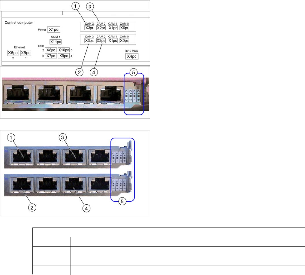
Hotlink card (PCI-A14 [03032343-xx])
The hotlink card is installed as a default with the box PC
627.
When installed, the version of the hotlink cards can only
be seen on the label for the camera connections (5).
(1) and (3): Stationary cameras for placement area 1
(X2pr and X3pr)
(2) and (4): Stationary cameras for placement area 2
(X2ps and X3ps)
In SIPLACE D1 machines, the FC camera is connected
to the hotlink card at terminal X3pr.
Hotlink card at box PC (PCI-A24 [03052135-xx])
In principle, the use of a hotlink card is possible from
SW605.03 (e.g. as spare part).
When installed, the version of the hotlink cards can only
be seen on the label for the camera connections (5).
(1) and (3): Stationary cameras for placement area 1
(X2pr and X3pr)
(2) and (4): Stationary cameras for placement area 2
(X2ps and X3ps)
Hotlink card
CAM0 Gantry 1 - PCB/component camera
CAM1 Gantry 2 - PCB/component camera (disconnected in D1 machines.)
CAM2 IC camera [03042343-xx] → cable X2pr
CAM3 FC camera [03042344-xx] → cable X3pr