00196608-01_AI_Stationaere_Kamera_Typ33_36_de_en.pdf - 第158页
Appendix Configuration of Stationary Camera with SIPLACE PRO Cameras Type 33 Fr om Version 03 To 07, Cameras Typ e 36 From Version 01 158 Stationary Camera Type 33/36 Stationäre Kamera Typ 33/ 36 4.3 Configuration of Sta…
Appendix
Cameras Type 33 From Version 03 To 07, Cameras Type 36 From Version 01 Camera Coding and Connections
Stationary Camera Type 33/36 Stationäre Kamera Typ 33/36 157
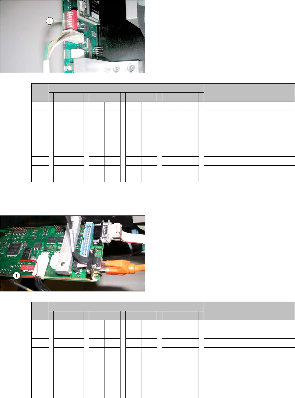
4.2.1.2 Coding the DIP Switch (8 Pin)
* Not all gantries may be available, depending on the machine type.
4.2.1.3 Coding the DIP Switch (6 Pin)
* Not all gantries may be available, depending on the machine type.
► Set the DIP switch (1) on the camera.
S Setting for gantry* Comments
1 2 3 4
1 OFF OFF OFF OFF Boot
2 OFF OFF OFF OFF Reset
3 OFF ON OFF ON Gantry ID 0
4OFFOFFONON Gantry ID 1
5 OFF OFF OFF OFF Test
6 OFF OFF OFF OFF CAN terminator
7ON ON ON ON 1 Mbit/s
8 xx xx xx x x x = OFF: FC camera (type 25)
x = ON: IC camera (type 33/36)
► Set the DIP switch (1) on the camera.
S Setting for gantry* Comments
1 2 3 4
1 OFF OFF OFF OFF Reset
2 OFF ON OFF ON Gantry ID 0
3OFFOFFONON Gantry ID 1
4 x x x x x x x x LED: This switch is delivered with
a fixed presetting. Do not change
this setting!
5 OFF OFF OFF OFF CAN terminator
6 x x x x x x x x x = OFF: FC camera (type 25)
x = ON: IC camera (type 33/36)
Appendix
Configuration of Stationary Camera with SIPLACE PRO Cameras Type 33 From Version 03 To 07, Cameras Type 36 From Version 01
158 Stationary Camera Type 33/36 Stationäre Kamera Typ 33/36
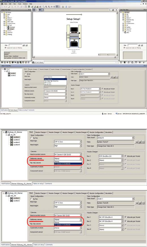
4.3 Configuration of Stationary Camera with SIPLACE PRO
Configuration of stationary camera (using example of D1)
► Select Setup → Location → Head tab and enter the
P&P head.
► Re-optimize the setup in SIPLACE Pro.
SIPLACE Pro setup (using example of X3)
SIPLACE Pro setup (using example of SX2)
Appendix
Up To Machine Series No. B325 Circuit Diagrams for X Series/D3
Stationary Camera Type 33/36 Stationäre Kamera Typ 33/36 159
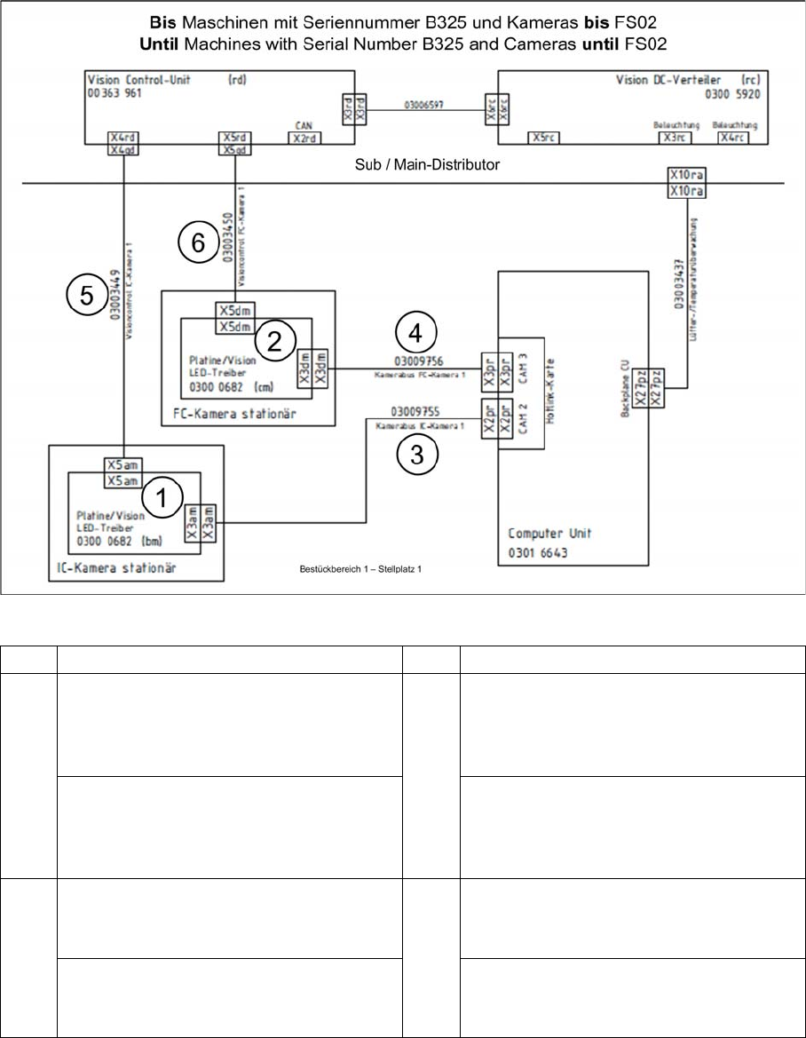
4.4 Circuit Diagrams for X Series/D3
4.4.1 Up To Machine Series No. B325
4.4.1.1 Camera Up To FS02
X series to serial no. B325 - camera to FS02
1 IC camera 2 FC camera
3 PA1: Cable camera bus IC camera 1
[03009755-xx]
To hotlink card 1 CAM2 (X2) (computer
unit)
4 PA1: Cable camera bus FC camera 1
[03009756-xx]
To hotlink card 1 CAM3 (X3) (computer
unit)
PA2: Cable camera bus IC camera 2
[03009757-xx]
To hotlink card 2 CAM2 (X2) (computer
unit)
PA2: Cable camera bus FC camera 2
[03009758-xx]
To hotlink card 2 CAM3 (X3) (computer
unit)
5 PA1: Cable vision control IC camera 1
[03003449-xx]
To subdistributor (X4qd)
6 PA1: Cable vision control FC camera 1
[03003450-xx]
To subdistributor (X5qd)
PA2: Cable vision control IC camera 2
[03003439-xx]
To main distributor (X4qd)
PA2: Cable vision control FC camera 2
[03003440-xx]
To main distributor (X5qd)