00196608-01_AI_Stationaere_Kamera_Typ33_36_de_en.pdf - 第126页
Installation Installation on X Series and D3 Machines Final Work 126 Stationary Camera Type 33/36 Stationäre Kamera Typ 33/ 36 3.2.4 Final Work ► Fit the camera hou sing. See a lso: "3.6.1 A ssembling th e Camera&qu…
Installation
Electrical Connections Installation on X Series and D3 Machines
Stationary Camera Type 33/36 Stationäre Kamera Typ 33/36 125
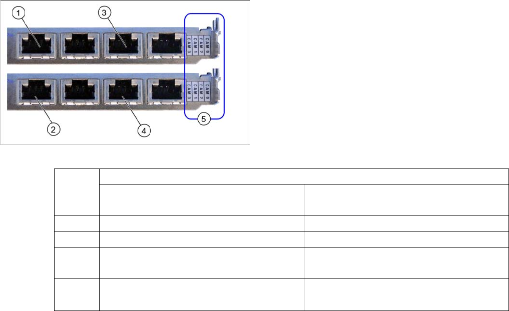
Hotlink card (PCI-A24 [03052135-xx])
The hotlink card is installed as a default with the box PC
627B up to approx. machine serial number B1125. in
principle, the use of a hotlink card is possible from
SW605.03 (e.g. as spare part).
When installed, the version of the hotlink cards can only
be seen on the label for the camera connections (5).
(1) and (3): Stationary cameras for placement area 1
(X2pr and X3pr)
(2) and (4): Stationary cameras for placement area 2
(X2ps and X3ps)
Hotlink cards
PA1
Card 1 (top)
PA2
Card 2 (bottom)
CAM0 Gantry 1 - PCB/component camera Gantry 2 - PCB/component camera
CAM1 Gantry 4 - PCB/component camera Gantry 3 - PCB/component camera
CAM2 Gantry 1 - stationary cameras (IC/FC)
→ Cable X2pr
Gantry 2 - stationary cameras (IC/FC)
→ Cable X2ps
CAM3 Gantry 4 - stationary cameras (IC/FC)
→ Cable X3pr
Gantry 3 - stationary cameras (IC/FC)
→ Cable X3ps

Installation
Installation on X Series and D3 Machines Final Work
126 Stationary Camera Type 33/36 Stationäre Kamera Typ 33/36
3.2.4 Final Work
► Fit the camera housing. See also: "3.6.1 Assembling the Camera" [ ➙ 149]
► Fit the "reject bin holder" and the corresponding sensors. See also: "3.6.3 Fitting the Component Re-
ject Bin" [ ➙ 150]
► Push the COT insert into its original position and screw tightly into place. Read the service manual
for your machine and section "3.2.4.1 COT Insert Assembly" [ ➙ 126] for more information.
► Hook the waste tape chute back into place.
► Fit the lower side cover by following the instructions in the reverse order, as described at Replacing
the Complete X Series Docking Unit [03015680-xx].
► Make sure that there are no objects in the hazard area of the gantry and remove any which are.
► Start the machine and move the component trolley back into the machine.
► Calibrate the machine. See also: "3.6.2 Calibrating the Camera" [ ➙ 150]
3.2.4.1 COT Insert Assembly
If you have moved the COT insert, fit it back into its original position and fit the side covers. Proceed as
follows:
► Move the COT insert into its final position (to the previously marked installation position).
Take care not to damage the cables and hoses.
► Loosely screw in the fitting screw and the fastening screws.
► Tighten the fitting screw first.
► Tighten the five fastening screws.
► Fit the side cover.
CAUTION
Service manual
► Read the section "Replacing the COT Insert" in your service manual!
CAUTION
Observe the specified order!
The fitting screw must be tightened first.
Installation
Installation Position D1 Assembly in a D1 Machine
Stationary Camera Type 33/36 Stationäre Kamera Typ 33/36 127
3.3 Assembly in a D1 Machine
General
The standard stationary camera for the SIPLACE D1 with a P&P module is the "component camera sta-
tionary P&P (type 36) 32x32 digit." [03042491-xx].
The "component camera stationary P&P (type 33) 55x45" provides a higher resolution (41 µm) and a
wider available component spectrum of up to 55x45 mm. This stationary camera can, for example, be
ordered if you require greater resolution than that offered by the standard camera or when you need to
place multiple components which are larger than 32x32 mm. The component spectrum for simple meas-
urement is from 0402 to 55x45 mm. The minimum lead pitch is 300 µm, the minimum lead width 150 µm,
the minimum ball pitch 350 µm and the minimum ball diameter 200 µm.
Prerequisites
When using a D1 with single head configuration, you need SW603-SP1. From SW604 onwards, this con-
figuration is already a fixed part of the software.
Required installation kits
See"2.3 Scope of Delivery" [ ➙ 102]
Installation kit: "stationary camera (type 33) 55x45 digital in the D1"
The stationary camera (type 36) is already included for a P&P module HRK used in D1 machines.
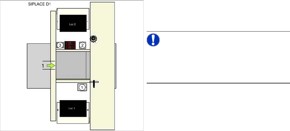
3.3.1 Installation Position D1
1. IC camera (type 36 or type 33)
2. FC camera
3. Component reject bin
NOTICE!
Type 36 or type 33
At position 1 there is a P&P module and type 36 IC cam-
era fitted as the standard camera. The type 33 camera is
optional.