00196608-01_AI_Stationaere_Kamera_Typ33_36_de_en.pdf - 第111页
Installation Mechanical Assembly Installation on X Series and D3 Machines Stationary Camera Typ e 33/36 Stationäre Kamera Typ 33/36 111 3.2.2 Mechanical Assembly NOTICE Configuration X2, X4 and D3 ► In the SIPLACE X2 the…
Installation
Installation on X Series and D3 Machines Installation Position X Series and D3
110 Stationary Camera Type 33/36 Stationäre Kamera Typ 33/36
3.2 Installation on X Series and D3 Machines
Required installation kits:
See"2.3 Scope of Delivery" [ ➙ 102]
Installation kit: stationary camera type 33 for CPP head fitted in X series [00119782-xx]
The stationary camera (type 33) is already included in the HRK for TwinHead used in X series machines.
3.2.1 Installation Position X Series and D3
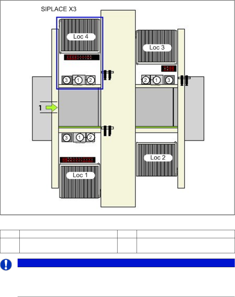
Installation position of cameras (using example of X3)
1 IC camera, type 33 3 Component reject bin
2 FC camera or 3D coplan Loc 1-
4
Location 1 - 4
NOTICE
TwinHead
The FC camera and the 3D coplan module are only possible together with a TwinHead. Only
one of these options can be fitted at this installation position, meaning that either the FC camera
or the 3D coplan module can be used.
Installation
Mechanical Assembly Installation on X Series and D3 Machines
Stationary Camera Type 33/36 Stationäre Kamera Typ 33/36 111
3.2.2 Mechanical Assembly
NOTICE
Configuration X2, X4 and D3
► In the SIPLACE X2 the cameras can be configured in PA1 in the same way as they are in
PA2 of SIPLACE X3 machines. In this case, location 1 equates to location 3.
► In the SIPLACE X4 the cameras can be configured in PA2 in the same way as they are in
PA1 of SIPLACE X3 machines. In this case, location 1 equates to location 3.
► The SIPLACE D3 can be configured in exactly the same way as the SIPLACE X3.
CAUTION
Observe the installation height
When fitting the camera, observe the correct installation height. Otherwise there will be a risk
of head crash!
► Please also observe section "4.1 Installation Height of the Stationary Camera" [ ➙ 153].
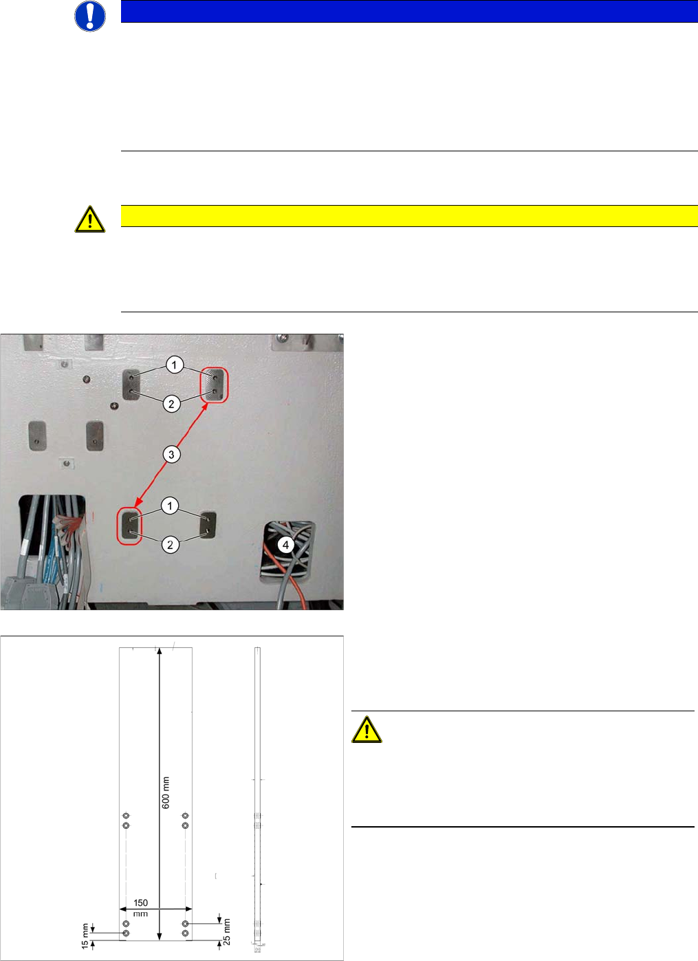
1. Upper position
2. Lower position
3. Position of grub screws for cameras up to FS05
4. Cable duct in machine base with camera cables
Fiducial sandwich plate [03022077-xx]
Suitable for IC camera type 33 and type 22
Use in SIPLACE X series, HF and D3 machines
CAUTION!
For assembly in X series and D3 machines, always use
the fiducial sandwich plate [03022077-xx]. If you do not,
machine accuracy will not be guaranteed and there is a
risk of a head crash occurring.
Installation
Installation on X Series and D3 Machines Mechanical Assembly
112 Stationary Camera Type 33/36 Stationäre Kamera Typ 33/36
3.2.2.1 Installation with Set Screws (for Camera Type 33 up to Version 05, Type 36 up to Version 03)
Camera in X series machine
► Screw the two set screws DIN913-M6x50-ST [03005958-xx] - with the Allen key side on the outside
- as assembly aid into the holes marked in the diagram:
Top holes: without C&P placement head
Bottom holes: with C&P placement head
► Fit the "fiducial sandwich plate" [03022077-xx] onto the set screws. Make sure that all eight holes
match the holes drilled in the machine frame. The set screws must protrude from the fiducial plate
by about 5 mm.
► Fit the camera base plate onto the "fiducial sandwich plate", so that the two set screws can be
reached. Screw the camera together with the base plate (two screws DIN912-M6x35-8.8
[00845062-xx]).
► Replace the two set screws with screws. If this is not possible, you will need to first remove the cam-
era and then move the set screws accordingly. Make sure that there is no set screw left behind the
camera as this could prevent the camera from being fitted firmly into place.
► Check the horizontal alignment of the camera with the machine spirit level.
DANGER
Sandwich plate for fiducial
The "fiducial sandwich plate" is very heavy and, when fitted, only clamped between the camera
and machine base. It can easily fall down, especially during removal.
► To prevent it falling down, proceed as follows:
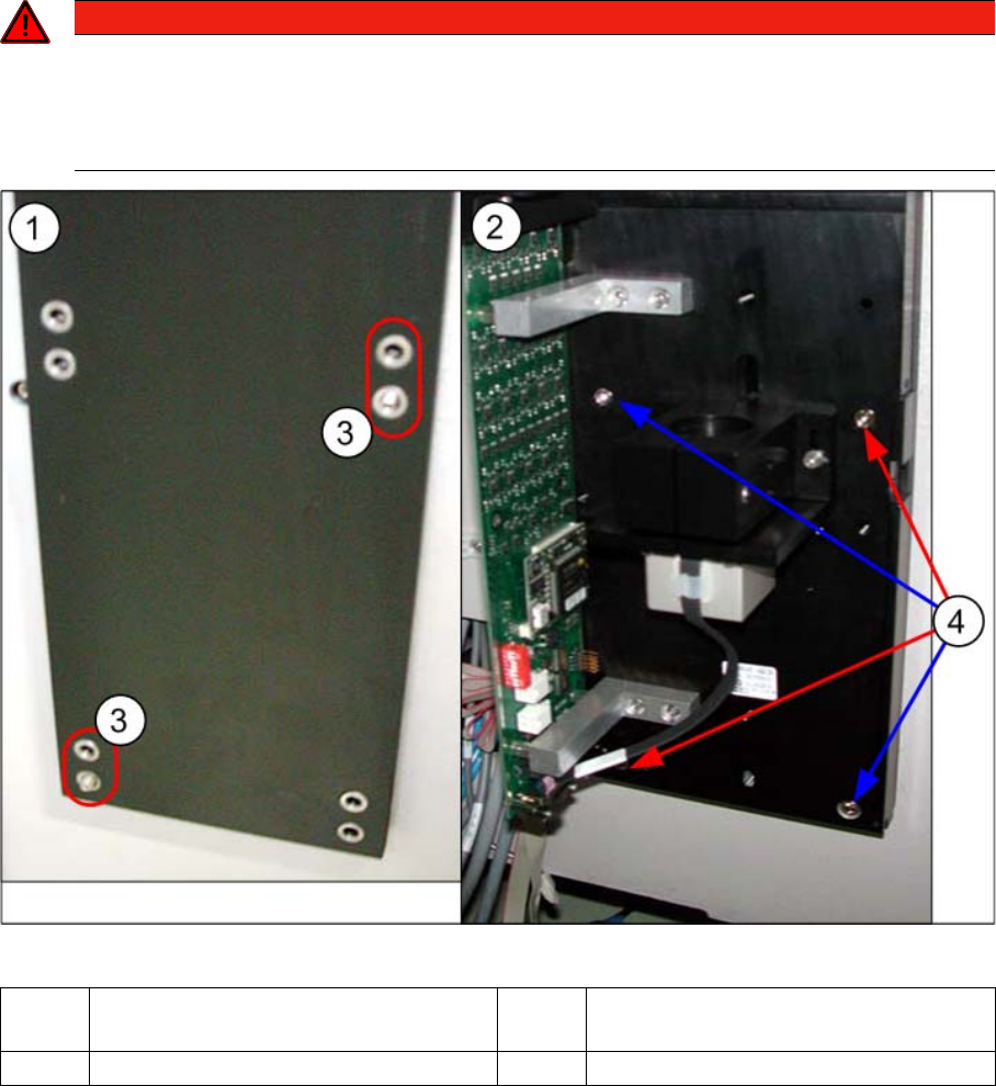
1 Diagram on left: fiducial plate – on set
screws.
2 Diagram on right: camera – on fiducial
plate and set screws.
3 Set screws 4 Positions of screws