00196608-01_AI_Stationaere_Kamera_Typ33_36_de_en.pdf - 第150页
Installation General Final Work Calibrating the Camera 150 Stationary Camera Type 33/36 Stationäre Kamera Typ 33/ 36 3.6.2 Calibrating the Cam era Calibrating the camera (SR70x.xx) ► Switch over to t he operator level Ma…
Installation
Assembling the Camera General Final Work
Stationary Camera Type 33/36 Stationäre Kamera Typ 33/36 149
3.6 General Final Work
The following tasks must be performed irrespective of the machine type:
3.6.1 Assembling the Camera
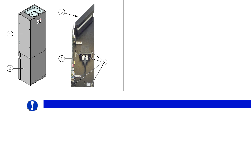
► Fit the housing for the lower section of the camera. This is either screwed or hooked into place, de-
pending on your camera type.
► Carefully place the camera upper section (illumination unit) on the camera lower section. Make sure
that the camera upper section is pushed in as far as the stop.
► Make sure that the glass surface is clean. Clean the mirror and glass surface with a microfiber cloth,
if necessary.
1. Camera upper section (illumination unit)
2. Camera lower section
3. Glass sheet
4. Camera electronics
5. Openings for fastening screws
NOTICE
The upper section of the camera has a fixed assignment to the bottom section of the camera!
The upper section of the camera may not be used with a different bottom section. Both the up-
per and lower sections are mechanically and electrically coordinated and may not be ex-
changed for use with other cameras. The serial and version numbers of the top and bottom
sections of the camera must be identical.
Installation
General Final Work Calibrating the Camera
150 Stationary Camera Type 33/36 Stationäre Kamera Typ 33/36
3.6.2 Calibrating the Camera
Calibrating the camera (SR70x.xx)
► Switch over to the operator level Machine service.
► Select Service (configure, update and calibrate the machine) --> Machine calibration.
► Select Head and cameras and click on Next.
► Select the relevant Gantry and click on Next.
► In the next step, the preconditions are checked. If these are fulfilled, click on Start.
Calibrating the camera (SR60x.xx)
► Start SITEST and perform camera calibration. See also the software guide for SITEST.
Firmware Download
3.6.3 Fitting the Component Reject Bin
When using the "stationary camera for CPP head" option, you need to fit an additional reject bin for com-
ponents > 36x36 mm. This is identical to the TwinHead reject bin.
This reject bin is included in the delivery packages for the stationary camera and the HRK for TwinHead.
Overview
NOTICE
Firmware download for cameras with 6-pin DIP switch (type 33 from version 07, type 36 from
version 05) and station software below 605.xx
The station software below 605.xx does not support the firmware download to these cameras.
SITEST shows a red cross in the relevant menu. However, the camera is still fully functional.
The red cross can be ignored.
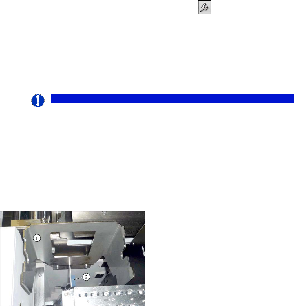
Holder for component reject bin (X series)
1. Holder for reject bins
2. Sensor for the component reject bin (optional)
Installation
Fitting the Component Reject Bin General Final Work
Stationary Camera Type 33/36 Stationäre Kamera Typ 33/36 151
Installation
► Fix the reject bin holder with 2 screws to the position shown on the machine frame.
► Fit the component reject bin into the holder.
3.6.3.1 Reject Bin Sensors
Note that the installation of an additional reject bin may also involve fitting sensors for the reject bin. For
more information, refer to the relevant assembly instructions.
▪ "Reject Bin Query X Series / D3, DE+EN" [00194716-xx] or
▪ "Reject Bin Query SX1/SX2, DE+EN" [00196615-xx]
The "stationary camera type 33 for CPP head in X series" [00119782-xx] contains an additional cable
with "reject bin sensors as extension kit" [03079029-xx]. In the SX series, these standard sensors are
already prepared for this configuration. Additional sensor cable are therefore not needed in this case.
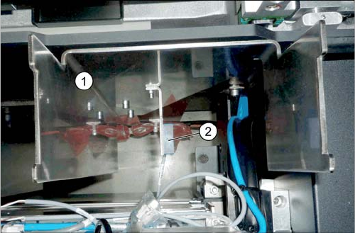
Holder for reject bins (SX1/SX2)
1. Holder for reject bins
2. Sensor for the component reject bin (optional)