00196608-01_AI_Stationaere_Kamera_Typ33_36_de_en.pdf - 第128页
Installation Assembly in a D1 Machine Mechanical Assembly 128 Stationary Camera Type 33/36 Stationäre Kamera Typ 33/ 36 3.3.2 Mechanical Assembly Equipment required: ▪ 2x set screw (DIN913-M6x50-ST) [03005958-xx] Dismant…
Installation
Installation Position D1 Assembly in a D1 Machine
Stationary Camera Type 33/36 Stationäre Kamera Typ 33/36 127
3.3 Assembly in a D1 Machine
General
The standard stationary camera for the SIPLACE D1 with a P&P module is the "component camera sta-
tionary P&P (type 36) 32x32 digit." [03042491-xx].
The "component camera stationary P&P (type 33) 55x45" provides a higher resolution (41 µm) and a
wider available component spectrum of up to 55x45 mm. This stationary camera can, for example, be
ordered if you require greater resolution than that offered by the standard camera or when you need to
place multiple components which are larger than 32x32 mm. The component spectrum for simple meas-
urement is from 0402 to 55x45 mm. The minimum lead pitch is 300 µm, the minimum lead width 150 µm,
the minimum ball pitch 350 µm and the minimum ball diameter 200 µm.
Prerequisites
When using a D1 with single head configuration, you need SW603-SP1. From SW604 onwards, this con-
figuration is already a fixed part of the software.
Required installation kits
See"2.3 Scope of Delivery" [ ➙ 102]
Installation kit: "stationary camera (type 33) 55x45 digital in the D1"
The stationary camera (type 36) is already included for a P&P module HRK used in D1 machines.
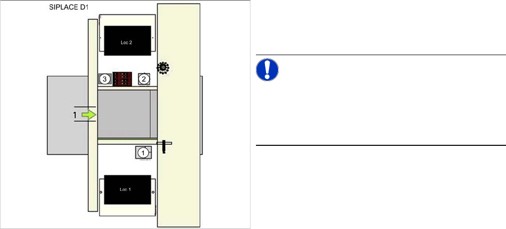
3.3.1 Installation Position D1
1. IC camera (type 36 or type 33)
2. FC camera
3. Component reject bin
NOTICE!
Type 36 or type 33
At position 1 there is a P&P module and type 36 IC cam-
era fitted as the standard camera. The type 33 camera is
optional.

Installation
Assembly in a D1 Machine Mechanical Assembly
128 Stationary Camera Type 33/36 Stationäre Kamera Typ 33/36
3.3.2 Mechanical Assembly
Equipment required:
▪ 2x set screw (DIN913-M6x50-ST) [03005958-xx]
Dismantling the existing camera
► Pull the illumination unit up and off the camera.
► Remove the bottom cover.
► Disconnect the camera from all electrical connections.
► Replace the top two fastening screws for the camera with set screws (DIN913-M6x50-ST
[03005958-xx]).
► Unscrew and remove the bottom two fastening screws on the camera.
► Take the camera base unit off the set screws. Take care that the fiducial sandwich plate does not
slip off the set screws.
CAUTION
Observe the installation height
When fitting the camera, observe the correct installation height. Otherwise there is a risk of
head crash!
► Please also observe section "4.1 Installation Height of the Stationary Camera" [ ➙ 153].
NOTICE
Same parts: camera type 33 and type 36
► For the D1 you can use the same screws and "sandwich plate for fiducial IC camera"
[03039370-xx] for both type 33 and type 36 stationary cameras.
► The "component reject assembly for P&P head" [03047406-xx] remains in the machine.
DANGER
Fiducial sandwich plate
The fiducial sandwich plate is very heavy and, when fitted, only clamped between the camera
and machine base.
Before removal, make sure that the sandwich plate does not fall down.
Installation
Mechanical Assembly Assembly in a D1 Machine
Stationary Camera Type 33/36 Stationäre Kamera Typ 33/36 129
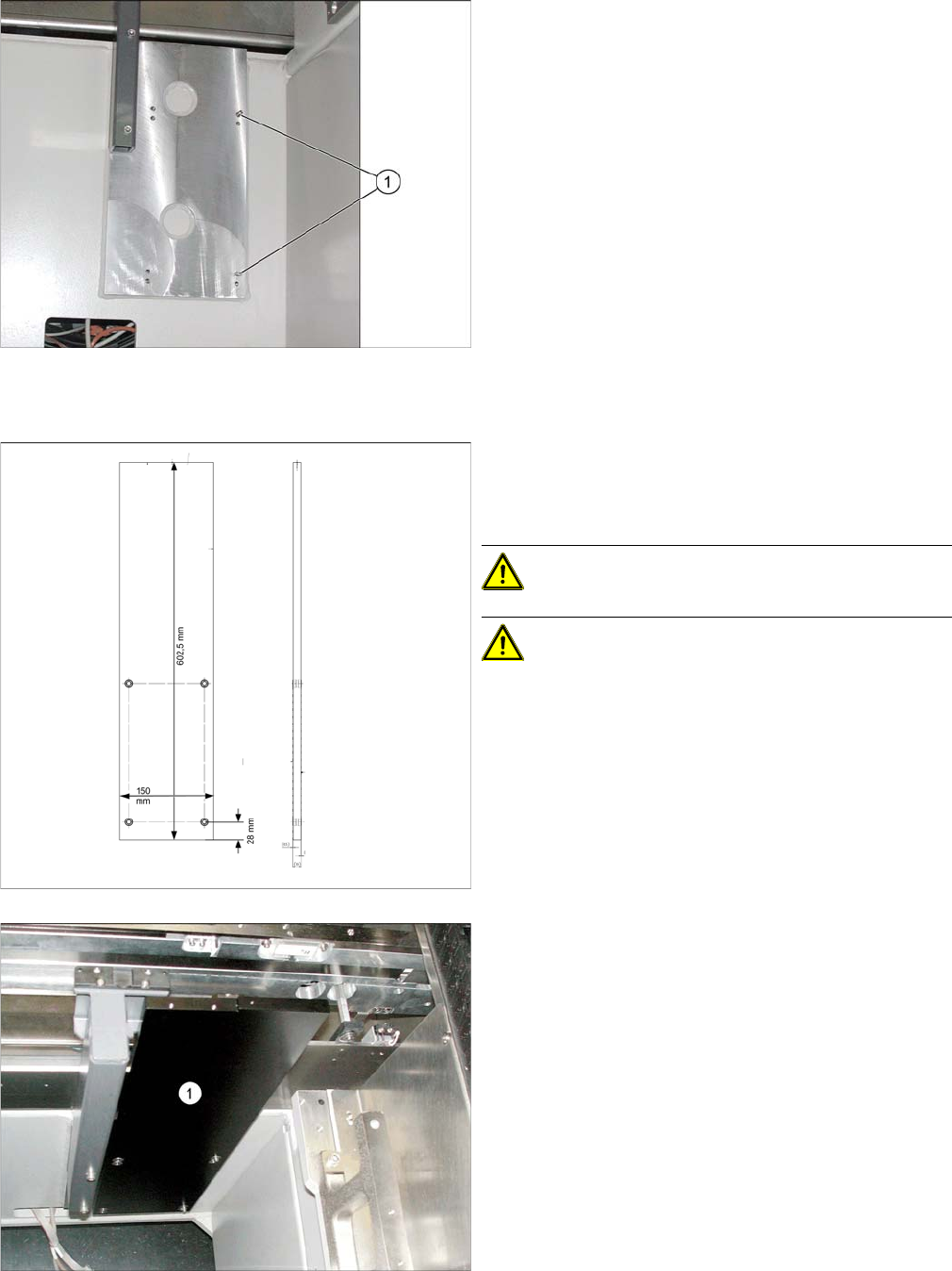
Fitting a new camera
Stationary camera - set screws (D1)
► Use the two set screws (1) as an assembly aid for the
camera fiducial plate and the camera base unit. The
Allen key side of the set screws must point to the out-
side, so that they can be unscrewed again.
Fiducial sandwich plate [03039370-xx]
Suitable for IC camera type 36 and type 33
Use in SIPLACE D1 machines
CAUTION!
CAUTION! For assembly in D1 machines, al-
ways use the fiducial sandwich plate [03039370-xx]. If
you do not, machine accuracy will not be guaranteed and
there will be a risk of a head crash occurring.
Stationary camera – sandwich plate (D1)
► Fit the fiducial sandwich plate onto the set screws.
These must exactly match the holes in the machine
frame and be fastened with the recess at the top left.