00196608-01_AI_Stationaere_Kamera_Typ33_36_de_en.pdf - 第76页
Anhang Konfiguration der stationären Kam era mit SIPLACE PRO Kameras Typ 33 ab Version 03 bis 07, Kameras Typ 36 ab Version 01 76 Stationary Camera Type 33/36 Stationäre Kamera Typ 33/36 4.3 Konfiguration der station äre…
Anhang
Kameras Typ 33 ab Version 03 bis 07, Kameras Typ 36 ab Version 01 Kameracodierung und Anschlüsse
Stationary Camera Type 33/36 Stationäre Kamera Typ 33/36 75
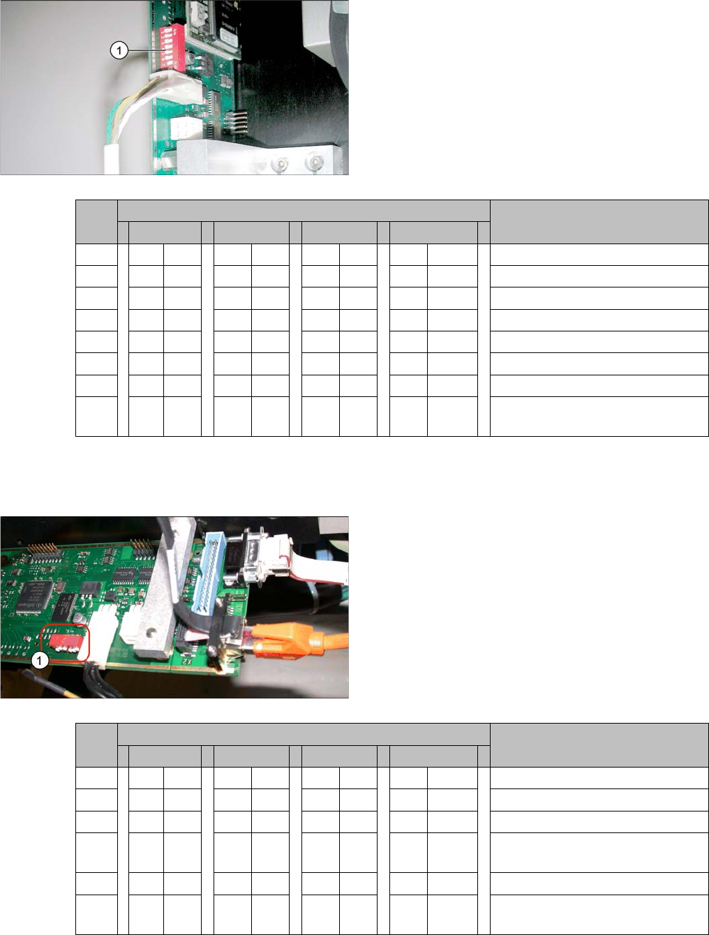
4.2.1.2 Kodierung des DIP-Schalters (8-polig)
* Je nach Maschinentyp sind nicht alle Portale verfügbar.
4.2.1.3 Kodierung des DIP-Schalters (6-polig)
* Je nach Maschinentyp sind nicht alle Portale verfügbar.
► Stellen Sie den DIP-Schalter (1) an der Kamera ein.
S Einstellung für Portal* Anmerkung
1 2 3 4
1 OFF OFF OFF OFF Boot
2 OFF OFF OFF OFF Reset
3 OFF ON OFF ON Portal-ID 0
4OFFOFFONON Portal-ID 1
5 OFF OFF OFF OFF Test
6 OFF OFF OFF OFF CAN-Terminator
7ON ON ON ON 1 Mbit/s
8 xx xx xx x x x = OFF: FC-Kamera (Typ 25)
x = ON: IC-Kamera (Typ 33/36)
► Stellen Sie den DIP-Schalter (1) an der Kamera ein.
S Einstellung für Portal* Anmerkung
1 2 3 4
1 OFF OFF OFF OFF Reset
2 OFF ON OFF ON Portal-ID 0
3OFFOFFONON Portal-ID 1
4 x x x x x x x x LED: Dieser Schalter wird vorein-
gestellt ausgeliefert. Nicht ändern!
5 OFF OFF OFF OFF CAN-Terminator
6 xx xx xx x x x = OFF: FC-Kamera (Typ 25)
x = ON: IC-Kamera (Typ 33/36)
Anhang
Konfiguration der stationären Kamera mit SIPLACE PRO Kameras Typ 33 ab Version 03 bis 07, Kameras Typ 36 ab Version 01
76 Stationary Camera Type 33/36 Stationäre Kamera Typ 33/36
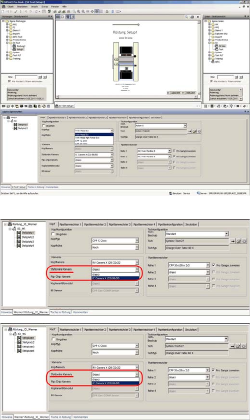
4.3 Konfiguration der stationären Kamera mit SIPLACE PRO
Konfiguration der stationären Kamera (am Beispiel D1)
► Wählen Sie Rüstung → Stellplatz → Registerkarte
Kopf und tragen Sie den P&P-Kopf ein.
► Optimieren Sie die Rüstung im SIPLACE Pro neu.
SIPLACE Pro Rüstung (am Beispiel X3)
SIPLACE Pro Rüstung (am Beispiel SX2)
Anhang
Bis Maschinen-Serien-Nr. B325 Stromlaufpläne X-Serie/D3
Stationary Camera Type 33/36 Stationäre Kamera Typ 33/36 77
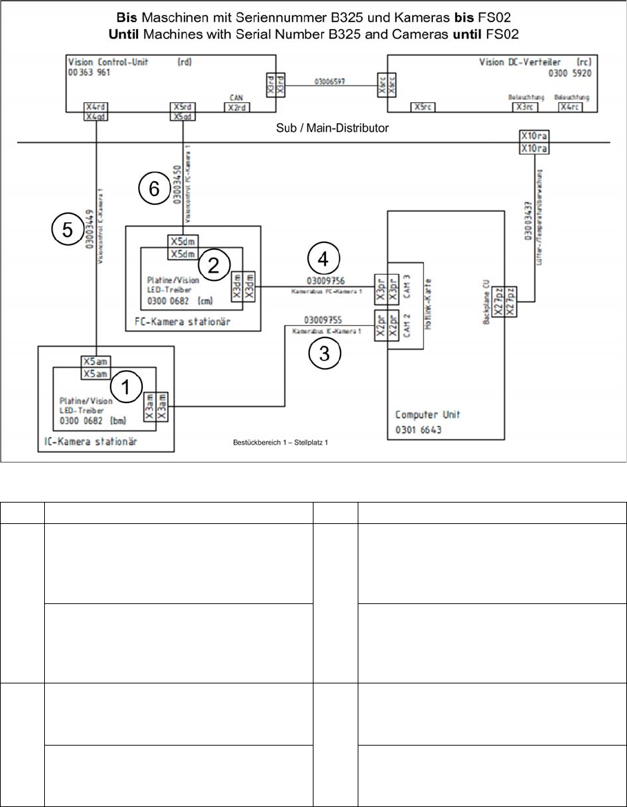
4.4 Stromlaufpläne X-Serie/D3
4.4.1 Bis Maschinen-Serien-Nr. B325
4.4.1.1 Kamera bis FS02
X-Serie bis Serien-Nr. B325 - Kamera bis FS02
1 IC-Kamera 2 FC-Kamera
3 BB1: Kabel Kamerabus IC-Kamera 1
[03009755-xx]
zur Hotlinkkarte 1 CAM2 (X2) (Computer-
Unit)
4 BB1: Kabel Kamerabus FC-Kamera 1
[03009756-xx]
zur Hotlinkkarte 1 CAM3 (X3) (Computer-
Unit)
BB2: Kabel Kamerabus IC-Kamera 2
[03009757-xx]
zur Hotlinkkarte 2 CAM2 (X2) (Computer-
Unit)
BB2: Kabel Kamerabus FC-Kamera 2
[03009758-xx]
zur Hotlinkkarte 2 CAM3 (X3) (Computer-
Unit)
5 BB1: Kabel Vision-Control IC-Kamera 1
[03003449-xx]
zum Sub-Distributor (X4qd)
6 BB1: Kabel Vision-Control FC-Kamera 1
[03003450-xx]
zum Sub-Distributor (X5qd)
BB2: Kabel Vision-Control IC-Kamera 2
[03003439-xx]
zum Main-Distributor (X4qd)
BB2: Kabel Vision-Control FC-Kamera 2
[03003440-xx]
zum Main-Distributor (X5qd)