00196608-01_AI_Stationaere_Kamera_Typ33_36_de_en.pdf - 第121页
Installation Electrical Connections Installation on X Series and D3 Machines Stationary Camera Typ e 33/36 Stationäre Kamera Typ 33/36 121 VCU without CAN bus and without TQM mo dule * Cameras with FS03 already have a CA…
Installation
Installation on X Series and D3 Machines Electrical Connections
120 Stationary Camera Type 33/36 Stationäre Kamera Typ 33/36
Connection of an IC Camera Stationary SST33 from FS03 to VCU (Up TO Serial Number 325)
NOTICE
Observe the machine serial number and camera FS number.
Observe this section for X series machines up to serial number B325 and IC cameras from
FS03.
NOTICE
CPP and VCU
The Vision Control Unit (VCU) does not support CPP heads. CPP heads and the corresponding
stationary cameras are therefore only possible from machine serial number B326.
► In this case, read the corresponding assembly instructions for information about further re-
strictions.
NOTICE
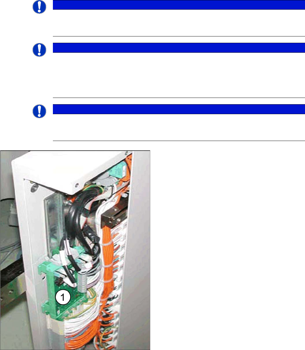
Control Unit 1 Vision, Stationary [00363961-xx]
The "Control Unit 1 Vision, Stationary" [00363961-xx] is part of the "Reconfig. parts kit parts kit
for X series/TwinHead" [03041487-xx].
► Fit the "Control Unit 1 Vision, Stationary" (1)
[00363961-xx] in the relevant slot.
The VCU for PA1 is located in the subdistributor (location
4).
The VCU for PA2 is located in the main distributor (loca-
tion 2).
Installation
Electrical Connections Installation on X Series and D3 Machines
Stationary Camera Type 33/36 Stationäre Kamera Typ 33/36 121
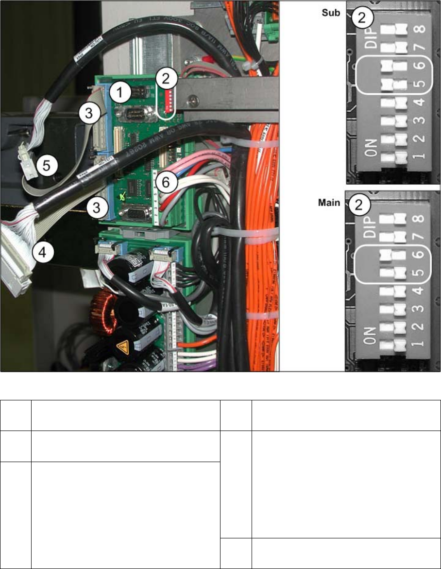
VCU without CAN bus and without TQM module
* Cameras with FS03 already have a CAN controller fitted. These cameras therefore do not need a VCU.
However, for reasons of downwards compatibility, you can still connect this type of camera to machines
with a VCU. To do this, you will need the "camera power adapter cable" [03059912-xx].
1 "Control Unit 1 Vision, Stationary"
[00363961-xx]
2 DIP switch VCU
3 Adapter cable for power to camera
[03059912-xx] *
4 PA1 subdistributor
Cable Vision Control IC camera 1
[03003449-xx]
to subdistributor (X4rd)
PA2 main distributor
Cable Vision Control IC camera 2
[03003439-xx]
to main distributor (X4rd)
5 PA1 subdistributor
Cable Vision Control FC camera 1
[03003450-xx]
to subdistributor (X5rd)
PA2 main distributor
Cable Vision Control FC camera 2
[03003440-xx]
to main distributor (X5rd)
6 Cable: Voltage supply "Control Unit 1 Vi-
sion, Stationary" (X3rd)
Installation
Installation on X Series and D3 Machines Electrical Connections
122 Stationary Camera Type 33/36 Stationäre Kamera Typ 33/36
► Set the DIP switch on the "Control Unit 1 Vision, Stationary" [00363961-xx]:
Subdistributor: 5 and 6 to ON and the others to OFF
Main distributor: 6 to ON and the others to OFF
► If present, disconnect the CAN bus cable (X2) from the "Control Unit 1 Vision, Stationary"
[00363961-xx].
► If present, remove the existing TQM module [03003536-xx] from the VCU [00363961-xx].
► Insulate the CAN bus cable with adhesive tape and fix this to the cable tree. This is needed to prevent
interference.
► If not already connected, plug in the voltage supply cable "Control Unit 1 Vision, Stationary" (6).
► Plug in the "camera power adapter cable" (3) [03059912-xx] between the "Control Unit 1 Vision, Sta-
tionary" (X4 or X5) [00363961-xx] and the black Vision control cable (4) and (5). See also the circuit
diagrams "4.4.1.2 Camera From FS03" [ ➙ 160].
See also
4.4.1 Up To Machine Series No. B325 [ ➙ 159]
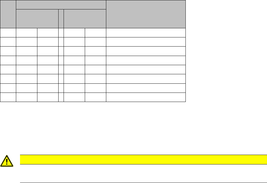
S1 Setting for placement area* Comments
1
(Sub)
2
(Main)
1 -- OFF -- OFF CAN terminator
2 -- OFF -- OFF Reset
3 -- OFF -- OFF Boot
4 -- OFF -- OFF CAN error switch
5ON -- -- OFF ID 1
6ON -- ON -- ID 2
7 -- OFF -- OFF CAN speed
8 -- OFF -- OFF CAN group
CAUTION
You must remove the CAN bus cable!
If you do not remove this cable, this could lead to CAN bus interference.