00196608-01_AI_Stationaere_Kamera_Typ33_36_de_en.pdf - 第34页
Einbau Montage an der X-Serie und D3 Elektrische Anschlüsse 34 Stationary Camera Type 33/36 Stationäre Kamera Typ 33/36 Anschluss an die Control-Unit-Vision-Stationär bis Serien-Nr. B 325 und IC-Kamera FS01 und FS02 HINW…
Einbau
Elektrische Anschlüsse Montage an der X-Serie und D3
Stationary Camera Type 33/36 Stationäre Kamera Typ 33/36 33
Sehen Sie dazu auch...
3.2.3.3 Anschließen der Hotlinkkabel an die ComputerUnit [ ➙ 41]
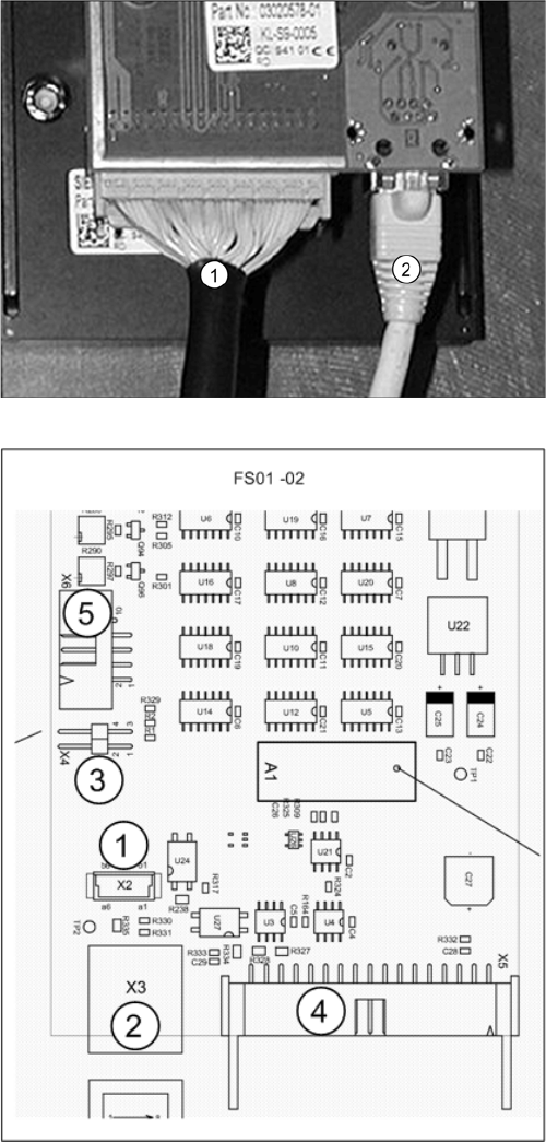
Kamera (FS02)
1. X5: Vision Kabel 34-polig, von IC-Kamera zur Con-
trol-Unit Vison Stationär
2. X3: Kabel vom Kamera-Bus zur ComputerUnit
► Schließen Sie das Kabel (1) an die Kamera an. Die-
ses stellt die Verbindung zur Control-Unit-Vison-
Stationär her.
► Schließen Sie das Kabel (2) an die Kamera an. Die-
ses stellt die Verbindung zur ComputerUnit her. Le-
sen Sie dazu im folgenden Abschnitt weiter: "3.2.3.3
Anschließen der Hotlinkkabel an die ComputerUnit"
[➙41]
Weitere Informationen entnehmen Sie bitte dem Strom-
laufplan: "4.4.1.1 Kamera bis FS02" [ ➙ 77]
Platine Vision-LED-Treiber SST20 (bis FS02)
1. X2: Nicht relevant
2. X3: Kabel Kamera-Bus zur ComputerUnit
3. X4: Jumper muss gesteckt sein
4. X5: Kabel: Vision Kabel 34 pol. IC-Kamera
[03003439-xx] zur Control-Unit-Vison-Stationär
5. X3: Nicht relevant
Einbau
Montage an der X-Serie und D3 Elektrische Anschlüsse
34 Stationary Camera Type 33/36 Stationäre Kamera Typ 33/36
Anschluss an die Control-Unit-Vision-Stationär bis Serien-Nr. B325 und IC-Kamera FS01 und FS02
HINWEIS
Maschinen-Serien-Nr. und Kamera-FS beachten
Dieser Abschnitt ist bei Maschinen der X-Serie bis Serien-Nr. B325 und IC-Kameras mit FS01
oder FS02 zu beachten.
HINWEIS
CPP und VCU
Die Vision-Control-Unit (VCU) unterstützt keinen CPP-Kopf. Daher sind der CPP-Kopf und ent-
sprechende stationäre Kameras erst ab Maschinen-Serien-Nr. B326 möglich.
► Lesen Sie in diesem Fall die entsprechende Montageanleitung, da noch weitere
Einschränkungen bestehen.
HINWEIS
TQM-Modul
Das TQM-Modul [03003536-xx] gehört nicht zum Lieferumfang der Kamera muss ggf. nachbe-
stellt werden.
HINWEIS
Controll-Unit 1 Vision stationär [00363961-xx]
Die "Controll-Unit 1 Vision stationär" [00363961-xx] ist Bestandteil des "Teilesatzes für ReCon-
fig X-Serie/TwinHead" [03041487-xx].
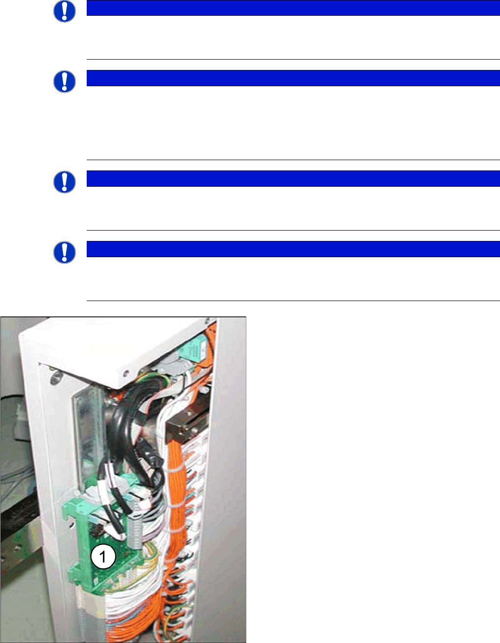
VCU
► Stecken Sie das TQM-Modul auf die Platine "Cont-
roll-Unit 1 Vision stationär" [00363961-xx].
► Montieren Sie die "Controll-Unit 1 Vision stationär"
[00363961-xx] mit aufgestecktem "TQM167 SI-
PLACE Embedded-Modul" [03003536-xx] im ent-
sprechenden Steckplatz (1).
▪ Die VCU des BB1 befindet sich im Sub-Distributor
(Stellplatz 4).
▪ Die VCU des BB2 befindet sich im Main-Distributor
(Stellplatz 2).
Einbau
Elektrische Anschlüsse Montage an der X-Serie und D3
Stationary Camera Type 33/36 Stationäre Kamera Typ 33/36 35
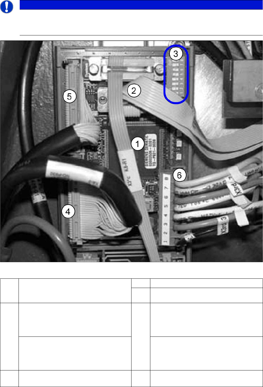
VCU mit CAN-Bus und TQM-Modul
► Schließen Sie den CAN-Bus (3) an X2 an.
► Schließen Sie das Spannungsversorgungskabel "Controll-Unit 1 Vision stationär" (6) an
HINWEIS
BIOS und eSW-Version
Kontrollieren sie nach dem Start der Maschine auch die BIOS- und Applikations-Version des
Visionsystems und aktualisieren Sie das System ggf. mittels eines SW-Downloads.
1 TQM-Modul [03003536-xx] auf
"Controll-Unit 1 Vision stationär"
[00363961-xx]
2 CAN-Bus-Kabel (X2rd)
3 DIP-Schalter VCU
4 BB1: Sub-Distributor
Kabel Vision-Control IC-Kamera 1
[03003449-xx]
zum Sub-Distributor (X4rd)
5 BB1: Sub-Distributor
Kabel Vision-Control FC-Kamera 1
[03003450-xx]
zum Sub-Distributor (X5rd)
BB2: Main-Distributor
Kabel Vision-Control IC-Kamera 2
[03003439-xx]
zum Main-Distributor (X4rd)
BB2: Main-Distributor
Kabel Vision-Control FC-Kamera 2
[03003440-xx]
zum Main-Distributor (X5rd)
6 Kabel:Spannungsversorgung "Controll-
Unit 1 Vision stationär" (X3rd)