00196608-01_AI_Stationaere_Kamera_Typ33_36_de_en.pdf - 第148页
Installation Installation on SX4 Machines Final Work 148 Stationary Camera Type 33/36 Stationäre Kamera Typ 33/ 36 3.5.4 Final Work ► Fit the camera hou sing. (See a lso "3.6.1 Assembling the Camera" [ ➙ 149])…
Installation
Electrical Connections Installation on SX4 Machines
Stationary Camera Type 33/36 Stationäre Kamera Typ 33/36 147
3.5.3.1 Connecting the Hotlink Cable to the BoxPC
► Connect your camera cable as follows:
CAUTION
Never connect a LAN cable to the hotlink card!
This could damage the hotlink card.
NOTICE
Connection for stationary cameras
► Observe section "4 Appendix" [ ➙ 153] and the latest circuit diagrams for your machine.
► When installed, the version of your hotlink card can only be determined by the position of
the camera connection label and the order of CAM connections.
► The stationary cameras are always connected to CAM2 or CAM3.
► The camera cables are labeled with their relevant connection details according to the pat-
tern X*p*.
CAUTION
Correctly connecting the camera cable
► Make sure that you connect the cameras correctly. Observe the labels on the hotlink cards.
If you do not observe this, placement performance may be adversely affected. Pay partic-
ular attention to the different order of connections on the PCI-A24!
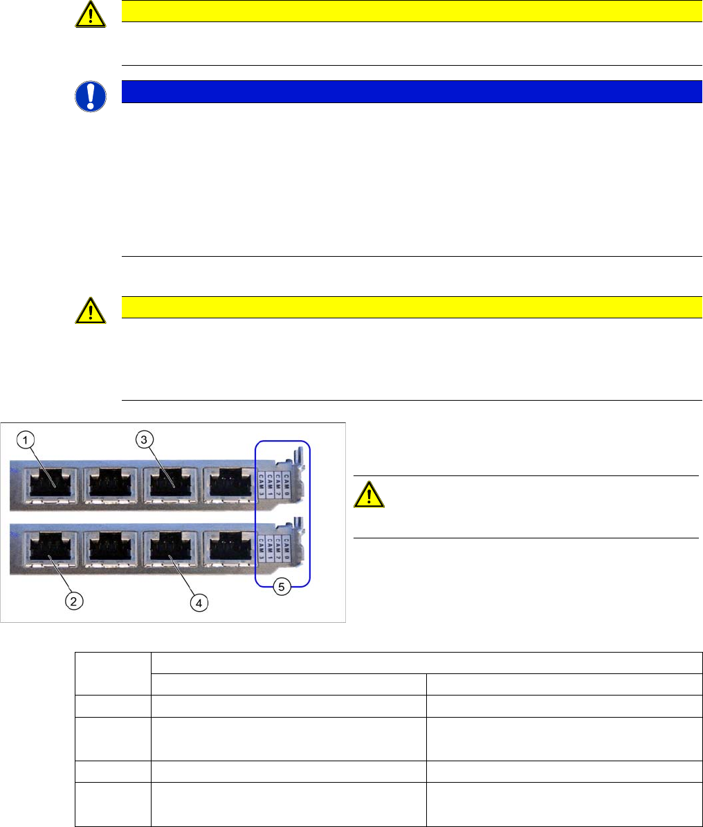
Hotlink card (PCI-A24 [03052135-xx])
The hotlink card is fitted in the SX4 as a default.
CAUTION!
Observe the order of camera connections (5)!
(1) and (3): Stationary cameras for placement area 1
(X2pr and X3pr)
(2) and (4): Stationary cameras for placement area 2
(X2ps and X3ps)
Hotlink cards
Card 1 (top) Card 2 (bottom)
CAM0 Gantry 1 - PCB/component camera Gantry 2 - PCB/component camera
CAM1 Not in use Gantry 2 - stationary cameras (IC/FC)
[03077048-xx] → cable X2ps
CAM2 Gantry 4 - PCB/component camera Gantry 3 - PCB/component camera
CAM3 Not in use Gantry 3 - stationary cameras (IC/FC)
[03077049-xx] → cable X3ps
Installation
Installation on SX4 Machines Final Work
148 Stationary Camera Type 33/36 Stationäre Kamera Typ 33/36
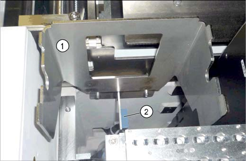
3.5.4 Final Work
► Fit the camera housing. (See also "3.6.1 Assembling the Camera" [ ➙ 149])
► If the reject bin sensor is present (2), you will need to fit this in a new position for the X series ma-
chine. For more information, refer to the relevant assembly instructions:
"Reject Bin Query X series/D3/SX4, DE+EN" [00194716-xx]
"Reject Bin Query SX1/SX2, DE+EN" [00196615-xx]
(See also "3.6.3 Fitting the Component Reject Bin" [ ➙ 150])
► Insert the "reject bin for TwinHead" [03072806-xx].
► Push the COT insert into its original position and screw tightly into place. Read the service manual
for your machine first.
► Hook the waste tape chute back into place.
► Fit the lower side cover. See alsoReplacing the Complete X Series Docking Unit [03015680-xx]
► Remove any objects from the travel range of the gantry and placement head.
► Start the machine and move the component trolley back into the machine.
► Calibrate the machine. (See also "3.6.2 Calibrating the Camera" [ ➙ 150])
Reject bin holder (example of X series shown)
► If not already present, fit the "reject bin holder" (1)
[03063283-xx] with two screws (DIN7984-M6x12-A2-
70) [03081847-xx].
Installation
Assembling the Camera General Final Work
Stationary Camera Type 33/36 Stationäre Kamera Typ 33/36 149
3.6 General Final Work
The following tasks must be performed irrespective of the machine type:
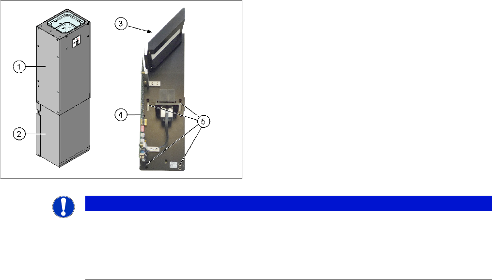
3.6.1 Assembling the Camera
► Fit the housing for the lower section of the camera. This is either screwed or hooked into place, de-
pending on your camera type.
► Carefully place the camera upper section (illumination unit) on the camera lower section. Make sure
that the camera upper section is pushed in as far as the stop.
► Make sure that the glass surface is clean. Clean the mirror and glass surface with a microfiber cloth,
if necessary.
1. Camera upper section (illumination unit)
2. Camera lower section
3. Glass sheet
4. Camera electronics
5. Openings for fastening screws
NOTICE
The upper section of the camera has a fixed assignment to the bottom section of the camera!
The upper section of the camera may not be used with a different bottom section. Both the up-
per and lower sections are mechanically and electrically coordinated and may not be ex-
changed for use with other cameras. The serial and version numbers of the top and bottom
sections of the camera must be identical.