00196608-01_AI_Stationaere_Kamera_Typ33_36_de_en.pdf - 第137页
Installation Mechanical Assembly Installa tion on SX1/SX2 Machines Stationary Camera Typ e 33/36 Stationäre Kamera Typ 33/36 137 Steel pins See also 4. 1 Installation Height of t he Stationary Camera [ ➙ 153] NOTICE …
Installation
Installation on SX1/SX2 Machines Mechanical Assembly
136 Stationary Camera Type 33/36 Stationäre Kamera Typ 33/36
3.4.3 Mechanical Assembly
Preparatory Steps
► Unhook the plate from the empty tape duct.
► If there is already a stationary FC camera present at the location, carefully pull the illumination unit
up and out and unhook the metal housing of the lower camera section.
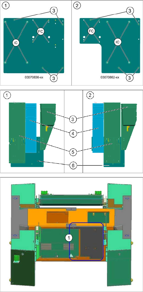
Support plates
1. Support plate location 1
2. Support plate location 2
3. Holes for fixing screws to the machine frame (4x
DIN912-M6x12-A2-70)
FC = FC camera (type 25)
IC = IC camera (type 33)
1. Location 1
2. Location 2
3. Reject bins
4. FC camera (type 25) with fiducial plate
5. IC camera (type 33)
6. Support plate
Surface for screwing to machine lower section
1. Surface for screwed fixture of support plate (location
2 shown here)
Installation
Mechanical Assembly Installation on SX1/SX2 Machines
Stationary Camera Type 33/36 Stationäre Kamera Typ 33/36 137
Steel pins
See also
4.1 Installation Height of the Stationary Camera [ ➙ 153]
NOTICE
Support plates
If there is no stationary camera installed at location 1, you will need a "support plate assembly
SP1" [03070836-xx].
For location 2 you need the "support plate assembly SP2" [03070862-xx].
The cameras and reject bin are fitted onto this.
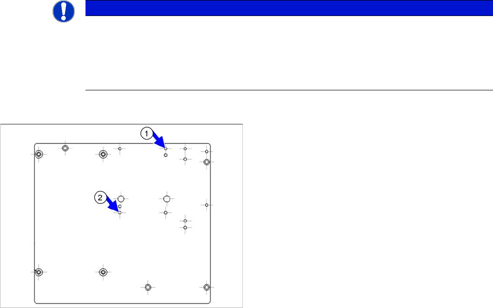
If not already present, you will need to knock two steel
pins [00311385-xx] into the support plate [03070836-xx].
► Carefully knock the steel pins into the two holes (1)
and (2) with the beveled side first. The steel pins
should protrude 8+/-1 mm out of the plate.
Installation
Installation on SX1/SX2 Machines Mechanical Assembly
138 Stationary Camera Type 33/36 Stationäre Kamera Typ 33/36
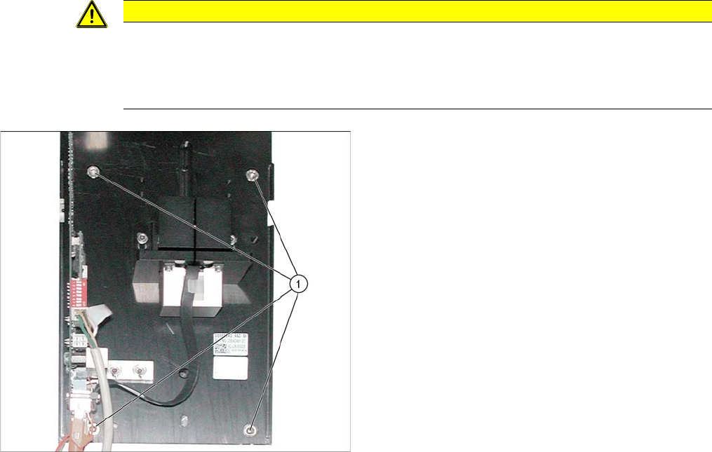
3.4.3.1 Installation of Camera with Set Screws (for Camera Type 33 up to Version 05)
CAUTION
Observe the installation height
When fitting the camera, observe the correct installation height. Othwerwise there is a risk of
head crash!
► Please also observe section "4.1 Installation Height of the Stationary Camera" [ ➙ 153].
► Screw the two set screws (with the Allen key side on
the outside) as assembly aid to the surface, on which
the camera is to be screwed. Select either the upper
or lower holes, depending on the installation height
required (1).
► Carefully push the lower section of the camera on to
the set screws.
► Fix the lower section of the camera with 2 screws to
the unused screw openings.
► Remove the two set screws and replace with 2 nor-
mal screws.
The lower section of the camera has now been fixed into
place.