00196608-01_AI_Stationaere_Kamera_Typ33_36_de_en.pdf - 第155页
Appendix Cameras Type 33 From Version 03 To 07, Cameras Type 36 From Ver sion 01 Camera Coding and Connections Stationary Camera Typ e 33/36 Stationäre Kamera Typ 33/36 155 4.2 Camera Coding and Connections See also …
Appendix
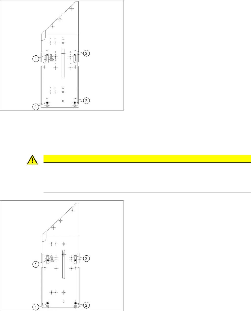
Installation Height of the Stationary Camera Stationary Camera in Position I
154 Stationary Camera Type 33/36 Stationäre Kamera Typ 33/36
4.1.1 Stationary Camera in Position I
4.1.2 Stationary Camera in Position II
Position II (middle) is not relevant for D, SX or X series machines.
4.1.3 Stationary Camera in Position III
If you are using a DLM or CPP head in a placement area,
fit the camera in the bottom position. This equates to po-
sition I.
1. Screw
2. Thread in the machine frame
Position I has to be used in the following cases:
▪ D series: always
▪ SX series: always
▪ X series: If at least one DLM or CPP head is used in
the corresponding placement area.
CAUTION
Danger of head crash
An incorrect installation height can result in a head crash!
If the camera is fitted at this height, only the TwinHead will be permitted for this placement area.
There is a risk of head crash otherwise!
If you are only using a TwinHead in this placement area,
fit the camera in the top position. This equates to position
III.
This installation position allows the movement of the Z
axis during component measurement to be omitted for
TwinHead operation, achieving higher placement perfor-
mance.
1. Screw
2. Thread in the machine frame
Position III must be used in the following cases:
▪ D series: never
▪ SX series: never
▪ X series: If solely TwinHeads are used in the corre-
sponding placement area.
Appendix
Cameras Type 33 From Version 03 To 07, Cameras Type 36 From Version 01 Camera Coding and Connections
Stationary Camera Type 33/36 Stationäre Kamera Typ 33/36 155
4.2 Camera Coding and Connections
See also
2.1.2 Version Overview [ ➙ 100]
4.2.1 Cameras Type 33 From Version 03 To 07, Cameras Type 36 From Version 01
General
In these cameras, the CAN controller is located directly on the driver board. However, this camera can
also be operated on the VCU. The connection is realized via the CAN bus for machines with a serial
number from approx. B326. The connection is still possible via the VCU for machines with a serial num-
ber below B326.
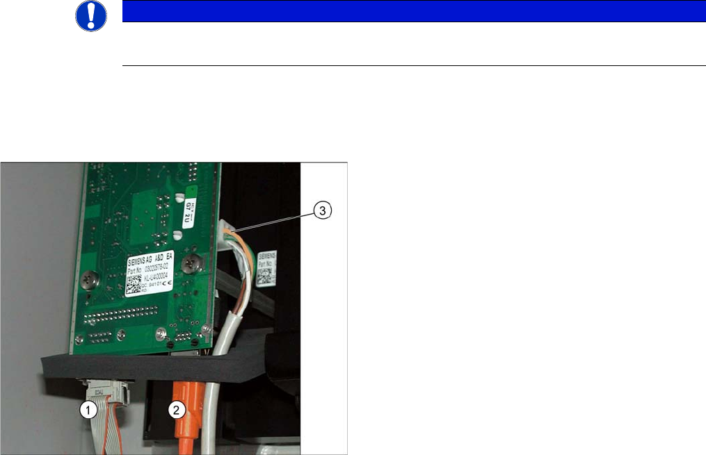
4.2.1.1 Camera Connection Board VLT33
For independent operation (not via the VCU), the camera cable, the CAN bus cable and the power sup-
ply are connected directly.
NOTICE
Coding the DIP switch
Newer cameras (type 33 from version 07, type 36 from version 05) have a 6-pin DIP switch.
1. CAN bus
2. Camera cable (hotlink cable)
3. Cable for power supply
Appendix
Camera Coding and Connections Cameras Type 33 From Version 03 To 07, Cameras Type 36 From Version 01
156 Stationary Camera Type 33/36 Stationäre Kamera Typ 33/36
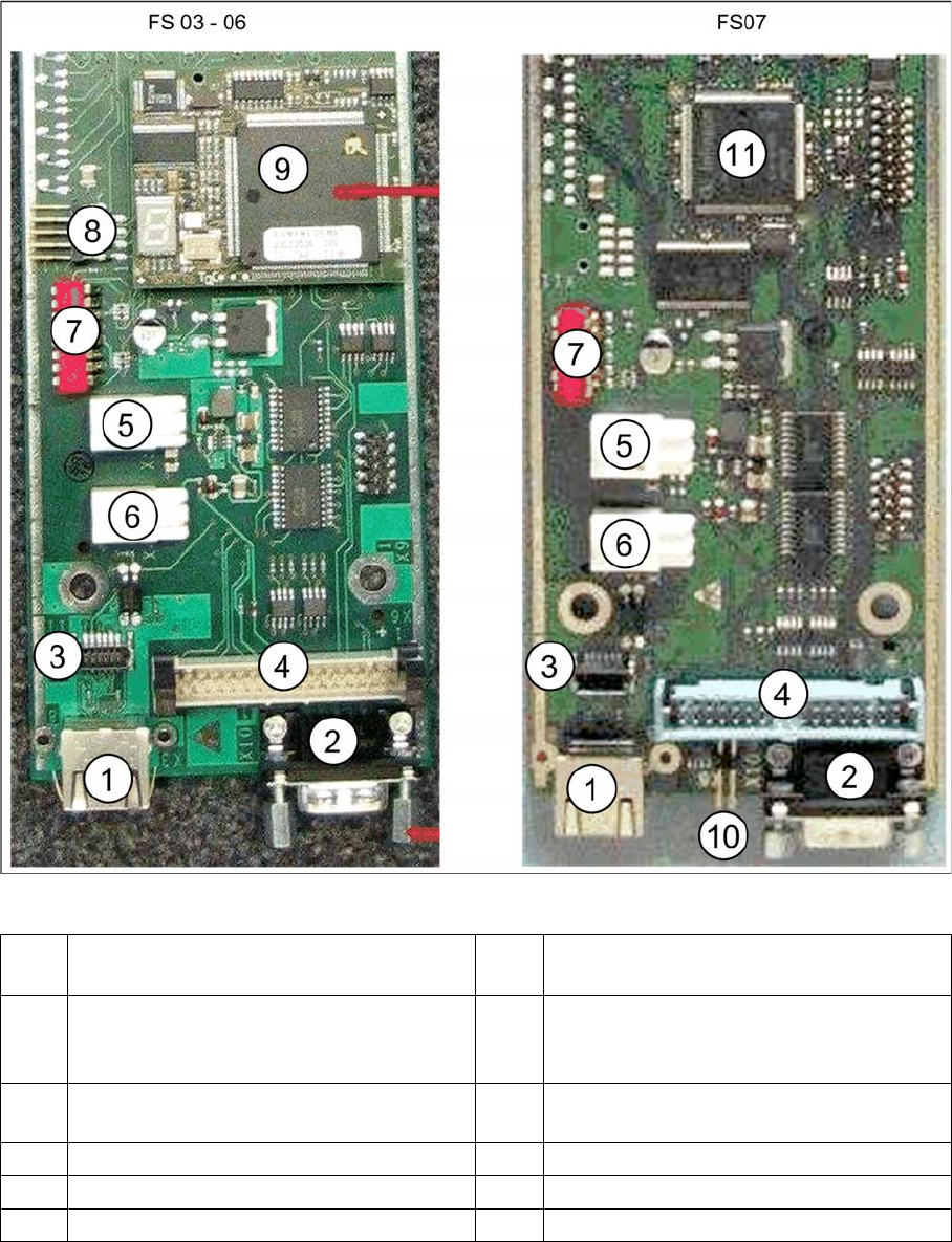
Vision LED driver board VLT33 from FS03
1 X3: Camera bus to station computer hotlink
card
2CAN bus
3 Not relevant 4 Vision cable 34-pin IC camera [03003439-
xx] to Vision controller
For machines up to serial number B326
5 X4: Cable for power supply 6 X5: Cable for power supply
Bridge to FC camera
7 DIP switch 8 Not relevant
9 Controller plug-in card FS03 to FS06 10 Not relevant
11 Controller onboard from FS07