00198599-02_AI_Vacuumpump_X-Series-S-from-Hxxxx_DE_EN.pdf - 第107页
107 Assembly Instructions / Montageanleitung SIPLACE X-Series S (from/ab Hxxxx) Option Vacuum Pump 02/2021 Contents Contents 1 Introduction .. 111 1.1 Safety instructions .. 111 1.1.1 Conventions for the use of safet…
7 Anhang
7.4 Auszüge aus der Serviceanleitung
106 Assembly Instructions / Montageanleitung SIPLACE X-Series S (from/ab Hxxxx) Option Vacuum Pump 02/2021
7.4.7.2 Schalldämpfer tauschen (nur Venturibetrieb)
Teile
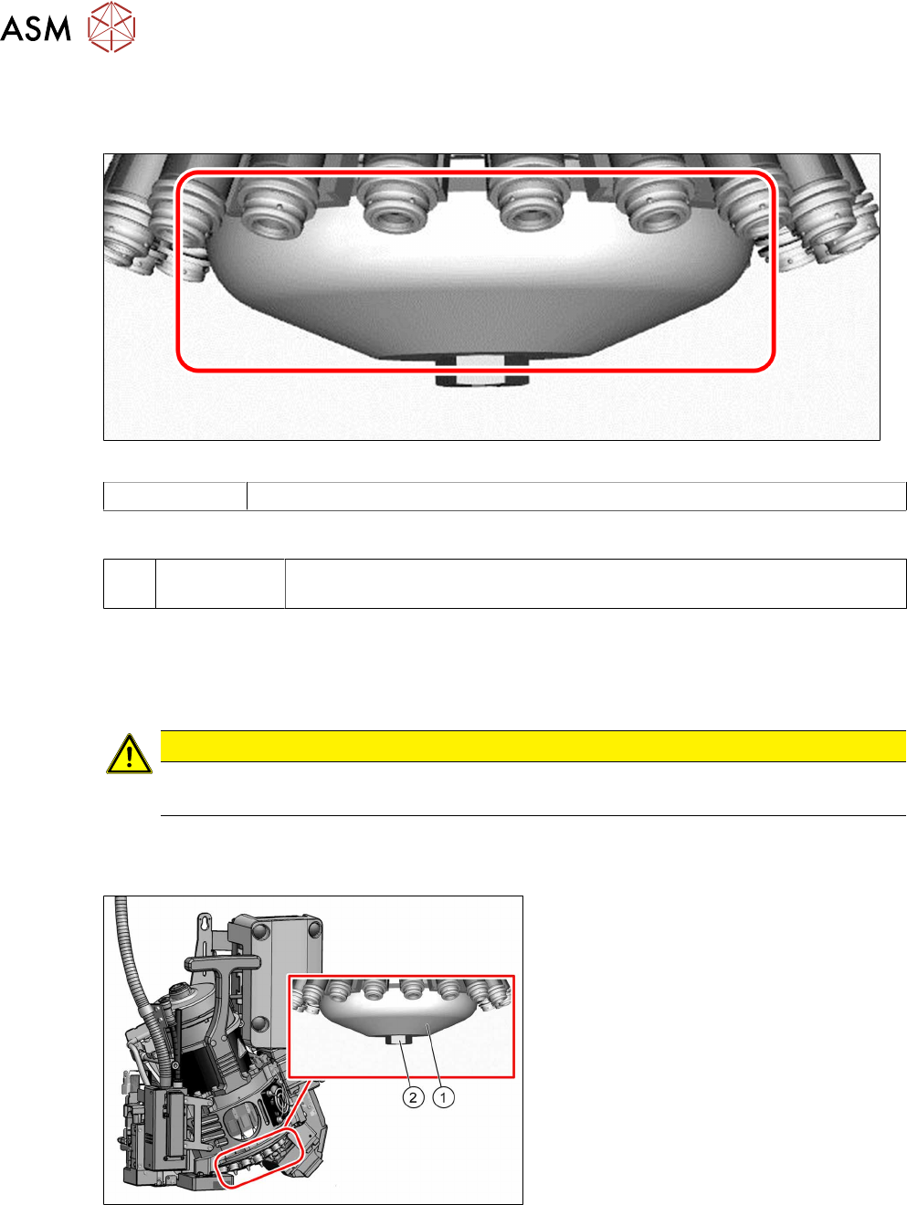
Abb.128: Schalldämpfer
03043707-xx Schalldämpfer
Hilfsmittel und Werkzeug
T --- Ggf. Werkzeug für den Aus- und Einbau sowie die Kalibrierung des
Bestückkopfes (siehe Serviceanleitung Ihrer Maschine)
Vorbereitung
► Bauen Sie den Kopf aus der Maschine aus. Für den Aus- und Einbau des Bestückkopfes
lesen Sie die Serviceanleitung Ihrer Maschine.
Montieren Sie den Kopf auf den Kopfständer [03056231‑xx].
VORSICHT
Kamera
► Achten Sie darauf, die Kamera-Optik nicht zu verschmutzen oder zu beschädigen.
► Stellen Sie sicher dass die BE-Sensorschutzkappe aufgesteckt ist.
Ausbau
Abb.129: Schalldämpfer
► Entfernen Sie die Befestigungs-
schraube(2)
des Schalldämpfers(1).
► Hebeln Sie den Schalldämpfer vorsich-
tig heraus.
Einbau
► Verfahren Sie für den Einbau in umgekehrter Reihenfolge. Beachten Sie dabei folgende Hinweise:
– Drücken Sie den neuen Schalldämpfer vorsichtig auf den Haltekreis.
– Schrauben Sie die Befestigungsschraube des Schalldämpfers mit der Hand vorsichtig
handfest
an.

107Assembly Instructions / Montageanleitung SIPLACE X-Series S (from/ab Hxxxx) Option Vacuum Pump 02/2021
Contents
Contents
1 Introduction.. 111
1.1 Safety instructions.. 111
1.1.1 Conventions for the use of safety instructions and symbols.. 111
1.1.2 Safety instructions for working with strong magnetic fields.. 112
1.1.3 Safety instructions for the power supply.. 112
1.1.4 Safety instructions for the compressed air supply.. 114
1.1.5 Safety instructions for work on the cutting device.. 114
1.1.6 Safety instructions for the gantry.. 114
1.1.7 Safety instructions on hazardous materials.. 115
1.2 Preparatory work..... 115
1.3 Other instructions.. 117
1.3.1 Environmentally-friendly disposal of materials and components.. 117
1.3.2 Use of original accessories and spare parts.. 117
1.3.3 ESD guidelines.. 117
1.3.3.1 What does ESD mean?.. 117
1.3.3.2 Important measures to protect against static charging.. 117
1.3.3.3 Handling ESD modules.. 117
1.3.3.4 Measurements and modifications to ESD modules.. 118
1.3.3.5 Dispatching ESD modules.. 118
1.3.4 Release History.. 118
1.4 Staff qualifications and training.. 118
1.5 Abbreviations.. 119
2 Brief description.. 121
2.1 Scope of delivery.. 122
2.1.1 Package for vacuum pump at PA1 (old vacuum pump).. 122
2.1.2 Package for vacuum pump at PA2 (old vacuum pump).. 123
2.1.3 Package for vacuum pump IE3 at PA1 (new vacuum pump).. 124
2.1.4 Package for vacuum pump IE3 at PA2 (new vacuum pump).. 125
2.1.5 Conversion kit 110V for vacuum pump IE3.. 125
2.1.6 Upgrade kit vacuum for standard gantries.. 126
2.1.7 Upgrade kit vacuum for rotated gantries.. 126
2.1.8 Fan plate.. 126
2.1.9 Vacuum valve/bypass converter.. 127
2.1.10 Conversion kit for vacuum pump operation in SIPLACE C&P20.. 127
2.1.11 Upgrade kit for pressure sensor vacuum in SIPLACE C&P20 P/P2/M2.. 127
2.1.12 Bridging plug.. 127
2.1.13 Support plate.. 127
2.2 Preconditions.. 128
2.3 Restrictions.. 128
2.4 Tools and equipment required.. 128
2.5 Vacuum pump - special features.. 129
3 Installation.. 131
3.1 Key information about the pneumatics and vacuum supply.. 131
3.2 Preparing the machine.. 132
3.3 Converting the gantries.. 133
3.3.1 Connecting the vacuum hoses to the placement head vacuum distributor.. 134

108 Assembly Instructions / Montageanleitung SIPLACE X-Series S (from/ab Hxxxx) Option Vacuum Pump 02/2021
Contents
3.3.2 Connecting the tubes and hoses.. 135
3.4 Converting the SIPLACE C&P20x.. 136
3.4.1 Removing the silencer.. 136
3.4.2 Removing the holding circuit.. 137
3.4.3 Fitting the aperture ring and the vacuum cover.. 138
3.4.3.1 Fitting the aperture ring and vacuum cover (SIPLACE C&P20A/M/P/M2).. 138
3.4.3.2 Fitting the aperture ring and vacuum cover (SIPLACE C&P20 P2).. 140
3.4.4 Installing the pressure sensor.. 142
3.5 Installing the vacuum pump.. 143
3.5.1 Preparing the vacuum pump.. 143
3.5.1.1 Preparing the vacuum pump (old).. 143
3.5.1.2 Preparing the vacuum pump (new).. 146
3.5.2 Installation locations of the vacuum pump.. 148
3.5.3 110 V (120 V) option.. 149
3.5.4 Running the supply cable.. 150
3.5.5 Preparing the vacuum distributor.. 153
3.5.5.1 Fitting the vacuum valve or bypass converter.. 154
3.5.6 Inserting the vacuum pump into the machine.. 155
3.5.6.1 Inserting the vacuum pump into the machine (old).. 155
3.5.6.2 Inserting the vacuum pump into the machine (new).. 156
3.5.7 Connecting the vacuum distributor to the pump.. 158
3.5.8 Installing the air box with exhaust air duct.. 159
3.5.9 Connecting and running tubes.. 160
3.5.10 Checking the direction of pump operation.. 162
3.5.11 Installing the fan plate.. 163
3.6 Final work.. 165
3.6.1 Docking the component trolley.. 165
3.6.2 Switch on machine.. 165
3.6.3 Checking the vacuum system of the holding circuit on a SIPLACE C&P20A/M/P for air-tightness..
166
4 Replacement.. 167
4.1 Spare parts.. 167
4.2 Replacement of old vacuum pump with new one.. 167
4.2.1 Parts required.. 167
4.2.2 Removal/installation.. 168
5 Converting to compressed air supply.. 169
6 Maintenance and service.. 171
7 Appendix.. 173
7.1 Arrangement of vacuum pumps and distributor.. 173
7.2 Circuit Diagrams.. 173
7.2.1 Tubes for gantry with vacuum pump.. 174
7.2.2 Vacuum pump at distributor.. 175
7.2.3 Old vacuum pump.. 176
7.2.3.1 Vacuum pump machine connection (old).. 176
7.2.3.2 Vacuum pump circuit diagram connection unit (old).. 177
7.2.3.3 Vacuum pump connection (old).. 178
7.2.4 New vacuum pump.. 179
7.2.4.1 Vacuum pump machine connection (new).. 179