00198599-02_AI_Vacuumpump_X-Series-S-from-Hxxxx_DE_EN.pdf - 第203页
7 Appendix 7.4 Excerpts from the service manual Assembly Instructions / Montageanleitung SIPLACE X-Series S (from/ab Hxxxx) Option Vacuum Pump 02/2021 203 Preparation ► Remove the head from the machine. For details about…
7 Appendix
7.4 Excerpts from the service manual
202 Assembly Instructions / Montageanleitung SIPLACE X-Series S (from/ab Hxxxx) Option Vacuum Pump 02/2021
Parts – compressed air operation
NOTICE
The SIPLACE C&P20P2 with compressed air mode had not been released by the time this
document was published.
► Contact the SIPLACE Service team for details.
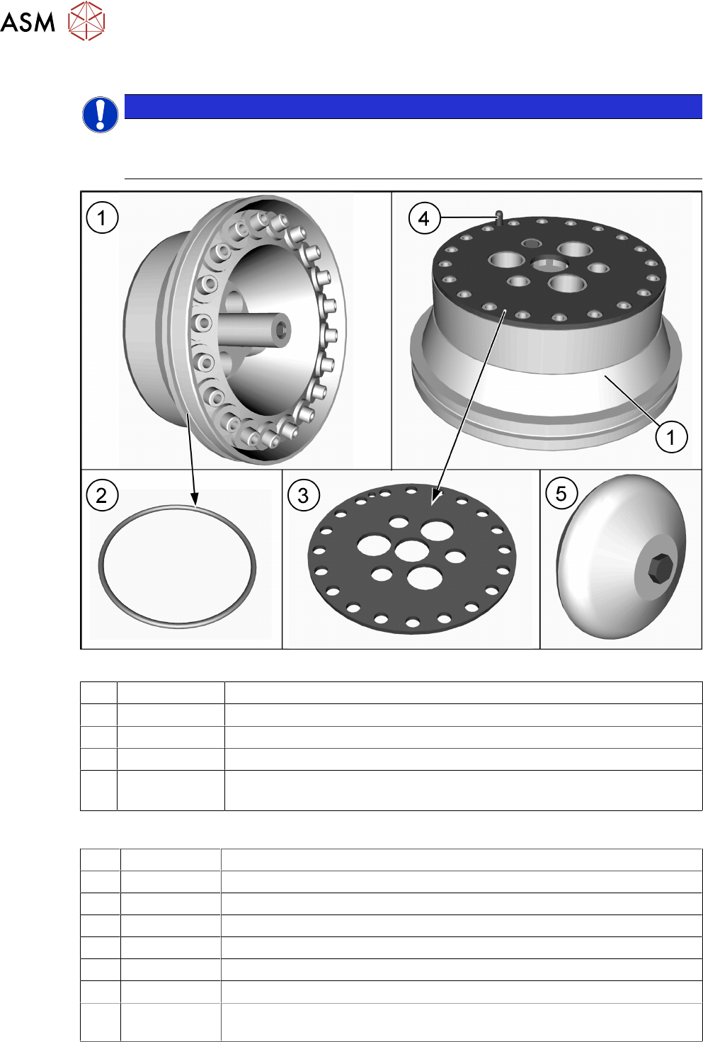
Fig.120: Holding circuit
1 03005123Sxx Holding circuit - vacuum unit
2 03046689-xx O-ring 50x1.5
3 03005120-xx Sealing disc for SIPLACE C&P20
4 --- Pins
5 03043707-xx Silencer assembly C&P20
See: 7.4.7.2 "Replacing the silencer (venturi mode only)" [}206]
Equipment and tools
T07 03078400-xx Torque Screwdriver ESD 1.0-5.0 Nm
T78 03090019-xx Torque interchangeable blades 2.5 mm, hexagonal
T98 03171857-xx Torque Allen swap blade 1.5 mm TX10
C03 03082092-xx Cleaning Wipe, KM-Wipe
C05 --- Isopropanol
C06 00352931-xx SIPLACE clean sticks
C11 03078517-xx ISOFLEX Topas 5051 50ml
T --- Tools for removing/fitting and calibrating the placement head, if needed
(see also the service manual for your machine)
7 Appendix
7.4 Excerpts from the service manual
Assembly Instructions / Montageanleitung SIPLACE X-Series S (from/ab Hxxxx) Option Vacuum Pump 02/2021 203
Preparation
► Remove the head from the machine. For details about removing and fitting the placement
head, refer to the service manual for your machine.
Fit the head on the head mount [03056231‑xx].
► Make sure that the component sensor protective cap is fitted.
Removal
NOTICE
Description example
The description uses the example of the aperture ring. The procedure for the holding circuit
is the same. Any relevant differences will be mentioned explicitly.
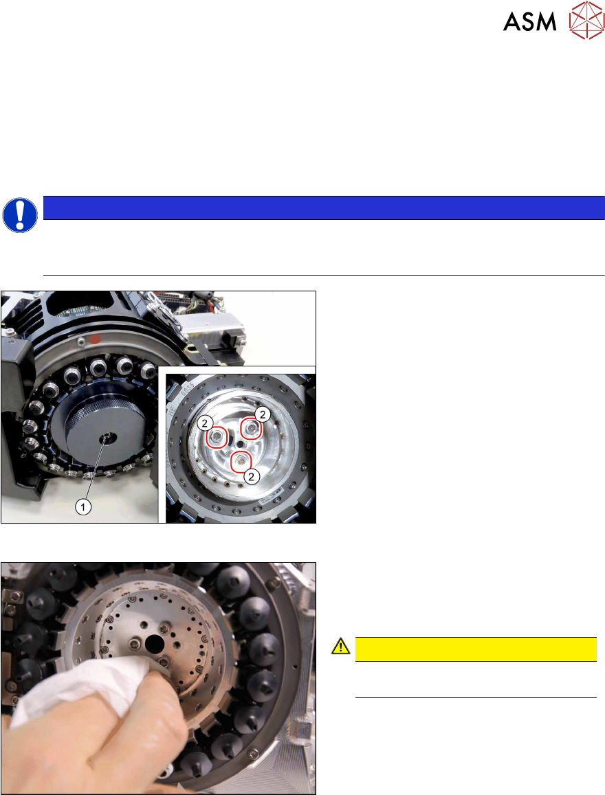
Fig.121: Dismantling the cover and aperture ring
► Remove the fastening screw(1) (TX10)
and then take off the cover.
► Remove the three screws(2) (TX10)
fastening the aperture ring.
► Carefully lever the aperture ring off the
locating pins. Make sure that the O-ring
is not damaged.
Fig.122: Cleaning
► Clean the seat of the aperture ring with
a cleaning cloth, coated with isopro-
panol.
CAUTION!
Do not use compressed air for
cleaning!
.
7 Appendix
7.4 Excerpts from the service manual
204 Assembly Instructions / Montageanleitung SIPLACE X-Series S (from/ab Hxxxx) Option Vacuum Pump 02/2021
Installation
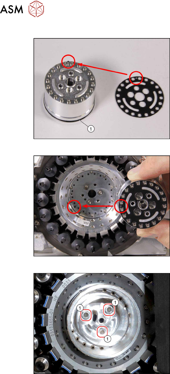
Fig.123: O‑Ring and sealing disc
► If the O-ring (1) is damaged, replace it
with a new one.
► Correctly position the sealing disc on
the aperture ring. Make sure all open-
ings are aligned. Pay attention to the
pin.
Fig.124: Inserting the aperture ring
► Position the aperture ring and sealing
disc correctly in the star carrier. Pay at-
tention to the pin.
Fig.125: Fasten the aperture ring
► Vacuum pump operation with aper-
ture ring only: Fix the aperture ring
with the three fastening screws (1)
(TX10, M3x10, torque 1.3 Nm).
► Venturi operation with holding cir-
cuit only: Fix the holding circuit into
place with the three fastening screws.
(TX10, M3x10, torque 0.25Nm
).