00198599-02_AI_Vacuumpump_X-Series-S-from-Hxxxx_DE_EN.pdf - 第166页
3 Installation 3.6 Final work 166 Assembly Instructions / Montageanleitung SIPLACE X-Series S (from/ab Hxxxx) Option Vacuum Pump 02/2021 3.6.3 Checking the vacuum system of the holding circuit on a SIPLACE C&P20A/ M…
3 Installation
3.6 Final work
Assembly Instructions / Montageanleitung SIPLACE X-Series S (from/ab Hxxxx) Option Vacuum Pump 02/2021 165
3.6 Final work
3.6.1 Docking the component trolley
► Fit the empty tape duct and fix into place with four screws, inserted from below and attached
to the assembly brackets on the left and right.
► Dock the component trolleys into place.
3.6.2 Switch on machine
CAUTION
Switch-on preconditions
Before switching on, perform the following checks to prevent injuries or serious damage to
property:
Make sure of the following before you switch the compressed air supply back on:
► Check that all hose connections are correctly assigned (also that there is no com-
pressed air in the vacuum hose).
► Check that all conditions for switch-on of the vacuum pump and connected placement
machine have been fulfilled, as specified in the user manuals.
► Open the compressed air shut-off valve.
► Close all doors.
► Switch the machine on at the main switch.
3 Installation
3.6 Final work
166 Assembly Instructions / Montageanleitung SIPLACE X-Series S (from/ab Hxxxx) Option Vacuum Pump 02/2021
3.6.3 Checking the vacuum system of the holding circuit on a SIPLACE C&P20A/
M/P for air-tightness
CAUTION
Minimum vacuum
At each placement machine/head there should be – depending on the nozzle configuration
– a vacuum of at least -500 mbar (for very large nozzles 1235) and -600 mbar (for very
small nozzles 1006)!
The measurement is performed at a nozzle, using an external device, which corresponds to
a closed nozzle (with component).
During operation, do not undershoot a vacuum of -400 mbar. If this still happens, please
contact your SIPLACE hotline.
Procedure
NOTICE
Avoid offset errors
To avoid offset errors, it can be advisable to perform both measurements with the same
measuring device.
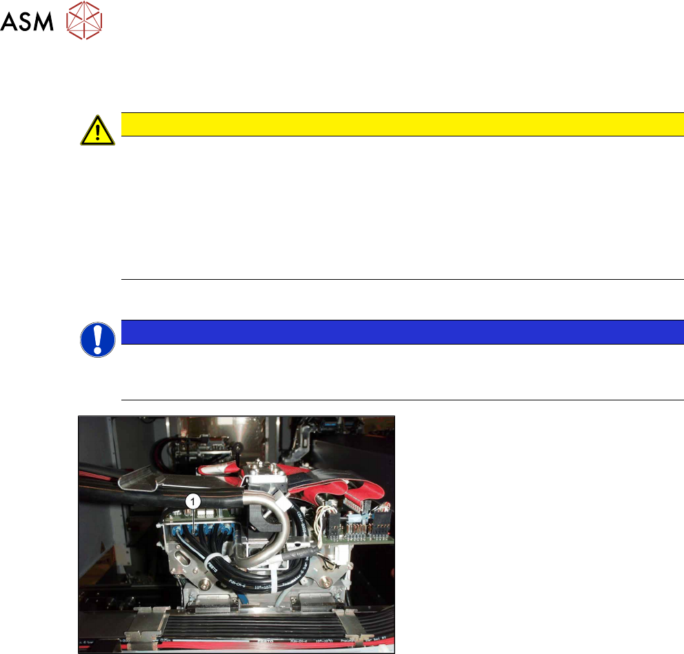
Fig.73: Connecting the "distributor placement head vacuum"
► Measure the vacuum with an external
pressure measuring device at a con-
nection(1)
of the "distributor placement
head vacuum".
► Measure the vacuum with an external
pressure measuring device at an open
nozzle in the holding circuit of the
placement head.
ð The pressure difference may only
be 30-50 mbar! If it exceeds this,
the system is not air-tight.
During the vacuum test, always measure at an open nozzle. In the case of large nozzles (1235),
the greater amount of escaping air usually makes the vacuum fall to values under -100 mbar. The
reason for this sharp drop – in the case of large nozzles without component – is the small reducing
nipple diameter in the aperture ring, compared to the nozzle diameter.
With a component, vacuum values of -500 to -600 mbar are achieved.
If the above mentioned values are not achieved, the cause is usually a hose in the head area which
has not been properly pushed on as far as the end stop. Proceed as follows:
► Use the hose pliers to push all hoses on properly.
► Repeat the vacuum measurement.
Checking the overall function of the hold circuit vacuum system
A vacuum test can be used to check the complete function of the vacuum system, as in the Venturi
principle.
The vacuum sensor in the hold circuit is only used to check whether the small nozzles in the aper-
ture ring are free of dirt.
4 Replacement
4.1 Spare parts
Assembly Instructions / Montageanleitung SIPLACE X-Series S (from/ab Hxxxx) Option Vacuum Pump 02/2021 167
4 Replacement
4.1 Spare parts
Replacement of spare parts follows the same procedure as that for fitting these parts.
Also observe the relevant chapter in section . 3 "Installation" [}131].
Some of the spare parts available are listed here:
Designation Item no.
Becker VX 4.25 IE3 vacuum pump with cable 03212135Sxx
Power circuit breaker 3RV20 3-pin 2.2-3.2A 03158435-xx
Cover fan, one part 03052317-xx
For information about other spare parts, please refer to the catalog of parts.
See also
2 6 "Maintenance and service" [}171]
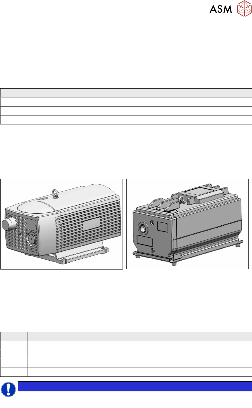
4.2 Replacement of old vacuum pump with new one
Fig.74: Old vacuum pump VX 4.25
Fig.75: New vacuum pump VX 4.25 IE3
When replacing an old vacuum pump [03128463‑xx] with a new one [03212135‑xx], observe the
instructions in the following chapters.
4.2.1 Parts required
Also observe section 2.1 "Scope of delivery" [}122].
To replace an old vacuum pump with a new one, you require the following parts:
Quantity Designation Item no.
Vacuum pump control SMPS 03218396Sxx
Vacuum pump IE3 1 X-Series S V2 03224400-xx
Vacuum pump IE3 2 X-Series S V2 03224402-xx
Conversion kit 110V for vacuum pump IE3 03224408Sxx
NOTICE
Replacing both pumps
If two old pumps are fitted, you will need to replace ´both when converting "old for new".