00198599-02_AI_Vacuumpump_X-Series-S-from-Hxxxx_DE_EN.pdf - 第132页
3 Installation 3.2 Preparing the machine 132 Assembly Instructions / Montageanleitung SIPLACE X-Series S (from/ab Hxxxx) Option Vacuum Pump 02/2021 3.2 Preparing the machine Before installing the pump, make sure that loc…

3 Installation
3.1 Key information about the pneumatics and vacuum supply
Assembly Instructions / Montageanleitung SIPLACE X-Series S (from/ab Hxxxx) Option Vacuum Pump 02/2021 131
3 Installation
CAUTION
Safety instructions and manufacturer's instructions
In addition to the safety instructions in the introductory chapter, the manufacturer's safety
instructions, installation and setup instructions apply to the vacuum pump and must be ob-
served.
NOTICE
Same procedure
The installation is usually shown using the example of the old vacuum pump version.
Installation of the new version follows the same procedure. Any relevant differences will be
mentioned explicitly.
3.1 Key information about the pneumatics and vacuum
supply
CAUTION
Compressed air
Never turn the compressed air on during the conversion, as this could lead to the place-
ment head being irreparably damaged, depending on the installation status.
The following diagram shows the conversion of a machine with two SIPLACE C&P20A/M/P to
vacuum pump operation.
A maximum of two SIPLACE C&P20A/M/P can be connected to one vacuum pump.
Preconditions (according to machine configuration) see 2.5 "Vacuum pump - special fea-
tures" [}129].
CAUTION
SIPLACE Twin and SIPLACE CPP
When using a SIPLACE Twin or CPP, never convert the pneumatic supply, gantry distrib-
utor or trailing cable! If you do, there is no guarantee that the SIPLACE Twin/CPP will func-
tion properly.
CAUTION
Switching the machine on and off
Avoid switching the machine and vacuum pump on and off multiple times within a short
period. This can have a negative influence on the service life of the pump.
The machine monitors when the vacuum pump is switched on and off (e.g. after longer production
standstill times).
3 Installation
3.2 Preparing the machine
132 Assembly Instructions / Montageanleitung SIPLACE X-Series S (from/ab Hxxxx) Option Vacuum Pump 02/2021
3.2 Preparing the machine
Before installing the pump, make sure that locations 1 to 4 are accessible.
► Undock the component trolleys from the relevant locations.
► Switch off the machine, disconnect it from the power supply and secure it to prevent
unauthorized reactivation.
1.2 "Preparatory work..." [}115]
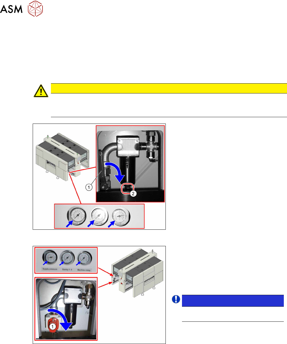
CAUTION
Switch off the compressed air supply
The compressed air supply must always be switched off for all work on the pneumatic sys-
tem.
Fig.4: Disabling the compressed air supply (version 1)
Version 1:
► Push the lever (1) for the compressed
air supply down until it is positioned ho-
rizontally.
► Open the screw (2) on the inlet filter to
vent the system. Hold a cloth under-
neath to capture any escaping liquid.
Fig.5: Shutting off the compressed air supply (version 2)
Version 2:
► Push the switch (1) for the compressed
air supply by 90 degrees, until it is posi-
tioned horizontally.
► All pressure gauges must be set to
zero.
NOTICE!
Venting is performed automatically
in this version.
.
► Dismantle the waste tape chute.
7.4.5 "Replacing the waste tape slide" [}193]
► Dismantle the cover plate for the vacuum pump installation.
3 Installation
3.3 Converting the gantries
Assembly Instructions / Montageanleitung SIPLACE X-Series S (from/ab Hxxxx) Option Vacuum Pump 02/2021 133
3.3 Converting the gantries
For conversion of the gantries to vacuum operation, you require the following upgrade kits:
●
1x upgrade kit vacuum X4i rotated [03075306‑xx] (gantry2 and4)
only for X4i S, one per gantry.
●
1x upgrade kit vacuum X-Series R10 [03075305] (gantries1 and3)
one per gantry on an X4i S
one per gantry on an X4S, X3S, X2S.
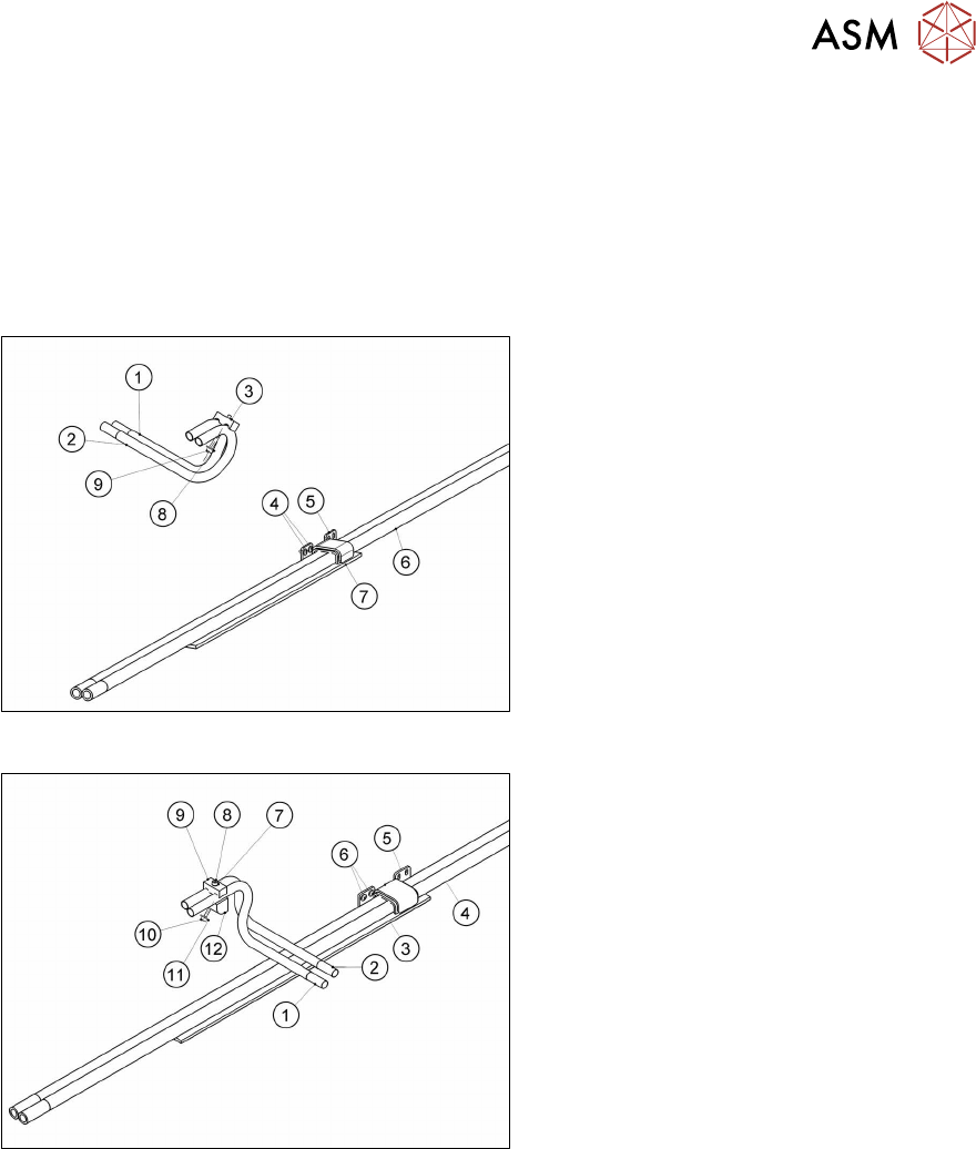
Fig.6: Upgrade kit vacuum X-Series R10
1. Tube for vacuum connection 1
2. Tube for vacuum connection 2
3. Clamping piece
4. Two screws (ISO7380-2 M3x6-A2-70)
(Loctite241)
5. Stabilizer damped
6. Duo hose
7. Foam rubber
8. One screw ISO7093-1-3-200HV-A2
9. One screw ISO4762-M3x35-A2-70
(Loctite241)
Fig.7: Upgrade kit vacuum X4i turned
1. Tube for vacuum connection 1 turned
2. Tube for vacuum connection 2 turned
3. Foam rubber
4. Duo hose
5. Stabilizer
6. Two screws ISO7380-2M3x6-A2-70
(Loctite241)
7. One screw ISO7089-2.5-200HV-A2
8. One screw ISO4762-M3x18-A2-70
(Loctite241)
9. Clamping piece
10. One screw ISO4762-M3x14-A2-70
(Loctite241)
11. One screw ISO7093-1-3-200HV-A2
12. Holder
The following section illustrates the conversion of a distributor for placement heads to vacuum
pump operation, using the example of gantry1/3.
See also
2 7.3 "Error message: 30356 Vacuum in holding circuit too low" [}183]