00198599-02_AI_Vacuumpump_X-Series-S-from-Hxxxx_DE_EN.pdf - 第161页
3 Installation 3.5 Installing the vacuum pump Assembly Instructions / Montageanleitung SIPLACE X-Series S (from/ab Hxxxx) Option Vacuum Pump 02/2021 161 Fig.64: Proportional controller (with tubes here instead of dummy …
3 Installation
3.5 Installing the vacuum pump
160 Assembly Instructions / Montageanleitung SIPLACE X-Series S (from/ab Hxxxx) Option Vacuum Pump 02/2021
3.5.9 Connecting and running tubes
For more information about the proportional controller, refer to section
7.4.1
"Replacing the proportional controller (pressure control valve) (location 4)" [}186].
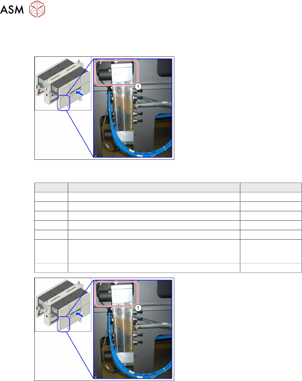
Fig.62: Proportional controller at location 4 (already without
hoses here, with dummy plugs)
Tasks on the proportional controller
Machines that are delivered with a vacuum
pump do not have the upper proportional
controller (1)
. A cover cap is fitted instead.
If the machine is to be converted to com-
pressed air operation, the proportional con-
troller must be retrofitted. The following
spare parts are required for this:
Quantity Designation Item no.
1 Proportional controller (pressure control valve) 03065425‑xx
1 O-Ring ID10 X 1.0 - NBR70 03031296‑xx
1 O-Ring ID20 X 1.0 - NBR70 03146099‑xx
1 O-Ring ID25 X 1.0 - NBR70 03146100‑xx
1 Sealing adapter plate proportional controller 03083211‑xx
1 Adapter plate top
or
Adapter plate bottom
03136076‑xx
or
03138952‑xx
5 ISO 10642 - M4x14-A2-70 03091400‑xx
Fig.63: Proportional controller (already without tubes here,
with dummy plugs)
We always recommend connecting the
tubes for a specific placement area one after
another to the vacuum pump. If you are con-
verting multiple gantries, disconnect/recon-
nect the tubes for one gantry at a time, to
prevent unintentional confusion of gantry
tube assignment.
► Localize the tube for the gantry to be
converted at the proportional controller
distributor (location4) and disconnect
this tube.
► Close the opening with a dummy
plug(1)
.
3 Installation
3.5 Installing the vacuum pump
Assembly Instructions / Montageanleitung SIPLACE X-Series S (from/ab Hxxxx) Option Vacuum Pump 02/2021 161
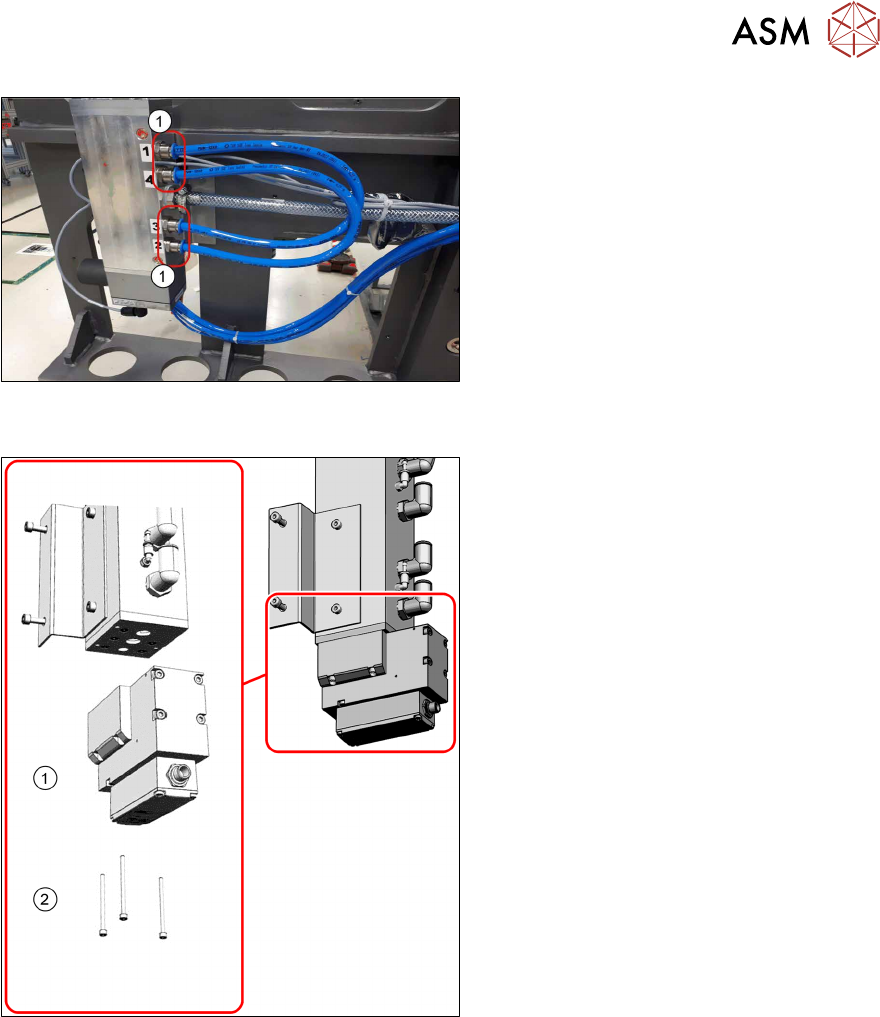
Fig.64: Proportional controller (with tubes here instead of
dummy plugs)
Proportional controller with tubes (1) instead
of dummy plugs.
Fig.65: Proportional controller
► Unplug the electrical connection to the
proportional controller(1)
.
► Remove the three screws(2) fastening
the proportional controller(1)
and then
lift the controller off.
The required tube-related tasks are performed either at location 1 or 4, depending on the installa-
tion location (see 3.5.2
"Installation locations of the vacuum pump" [}148] and 3.5.5 "Preparing the
vacuum distributor" [}153]).
3 Installation
3.5 Installing the vacuum pump
162 Assembly Instructions / Montageanleitung SIPLACE X-Series S (from/ab Hxxxx) Option Vacuum Pump 02/2021
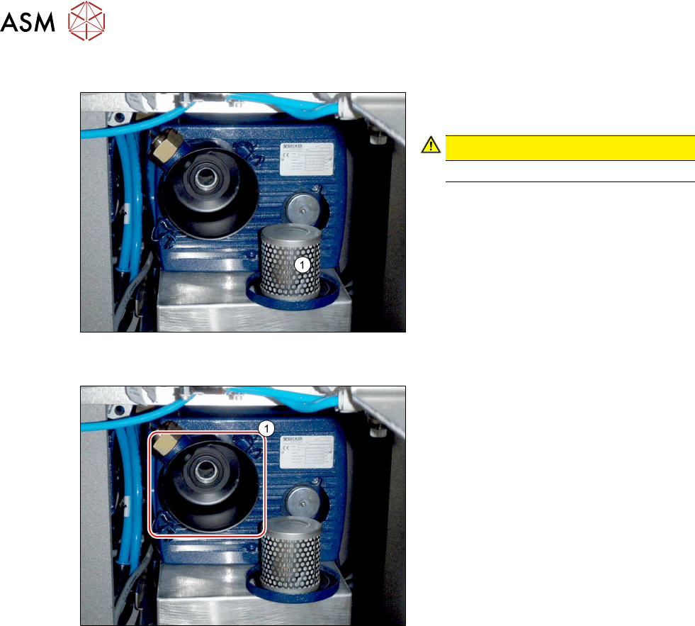
3.5.10 Checking the direction of pump operation
Fig.66: Removing the filter (example of old vacuum pump
shown)
► Open the brackets holding the filter
cover and remove the filter(1)
.
CAUTION!
Do not reach into the pump!
.
► Switch the machine on at the main
switch. The vacuum pump must also
switch itself on, although this might not
occur immediately after the machine is
switched on.
Fig.67: Suction opening (example of old vacuum pump
shown)
► Hold a hand or sheet of paper in front
of the suction opening of the pump(1).
ð The pump must be sucking air into
the machine!
► If the pump is running in the wrong direction, disconnect the entire system from the voltage
supply. Unplug the vacuum pump from the power.
– If both connections for the vacuum pump show the same effect, rewire the network cable
connection in the connection unit (exchange two phases - 24 Volt in the Mine Mad BN
Lock plug).
– If only one vacuum pump is running incorrectly, rewire at the relevant vacuum pump (ex-
change two phases - 24 Volt in the Mini Mad BN Lock plug).
► Return the filter.
► Check the connections for air-tightness. Make sure that they are not sucking in air incorrectly.