00198599-02_AI_Vacuumpump_X-Series-S-from-Hxxxx_DE_EN.pdf - 第152页
3 Installation 3.5 Installing the vacuum pump 152 Assembly Instructions / Montageanleitung SIPLACE X-Series S (from/ab Hxxxx) Option Vacuum Pump 02/2021 Detailed circuit diagram vacuum pump (new) Fig.44: Detailed circui…
3 Installation
3.5 Installing the vacuum pump
Assembly Instructions / Montageanleitung SIPLACE X-Series S (from/ab Hxxxx) Option Vacuum Pump 02/2021 151
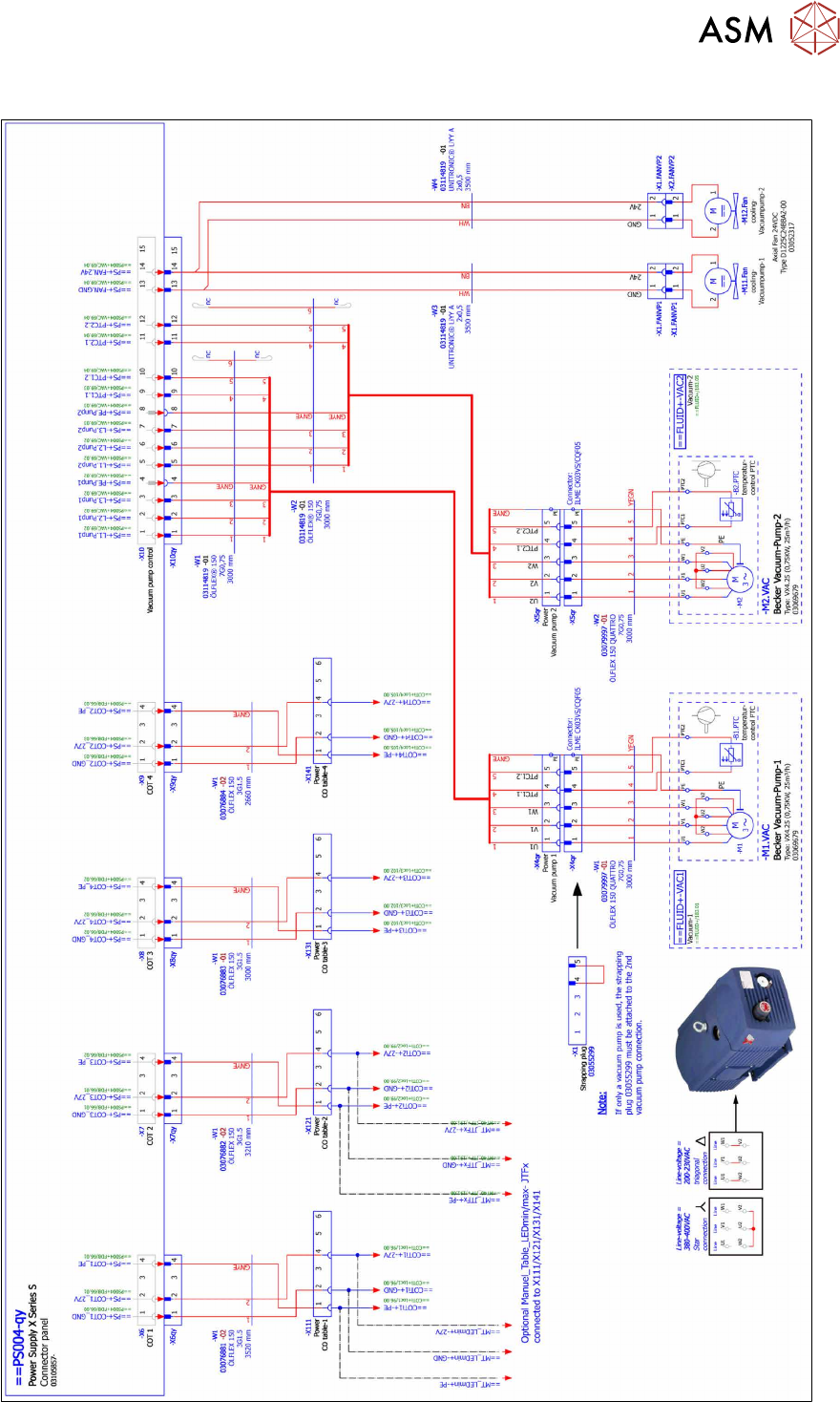
Detailed circuit diagram vacuum pump (old)
Fig.43: Detailed circuit diagram vacuum pump (old)
3 Installation
3.5 Installing the vacuum pump
152 Assembly Instructions / Montageanleitung SIPLACE X-Series S (from/ab Hxxxx) Option Vacuum Pump 02/2021
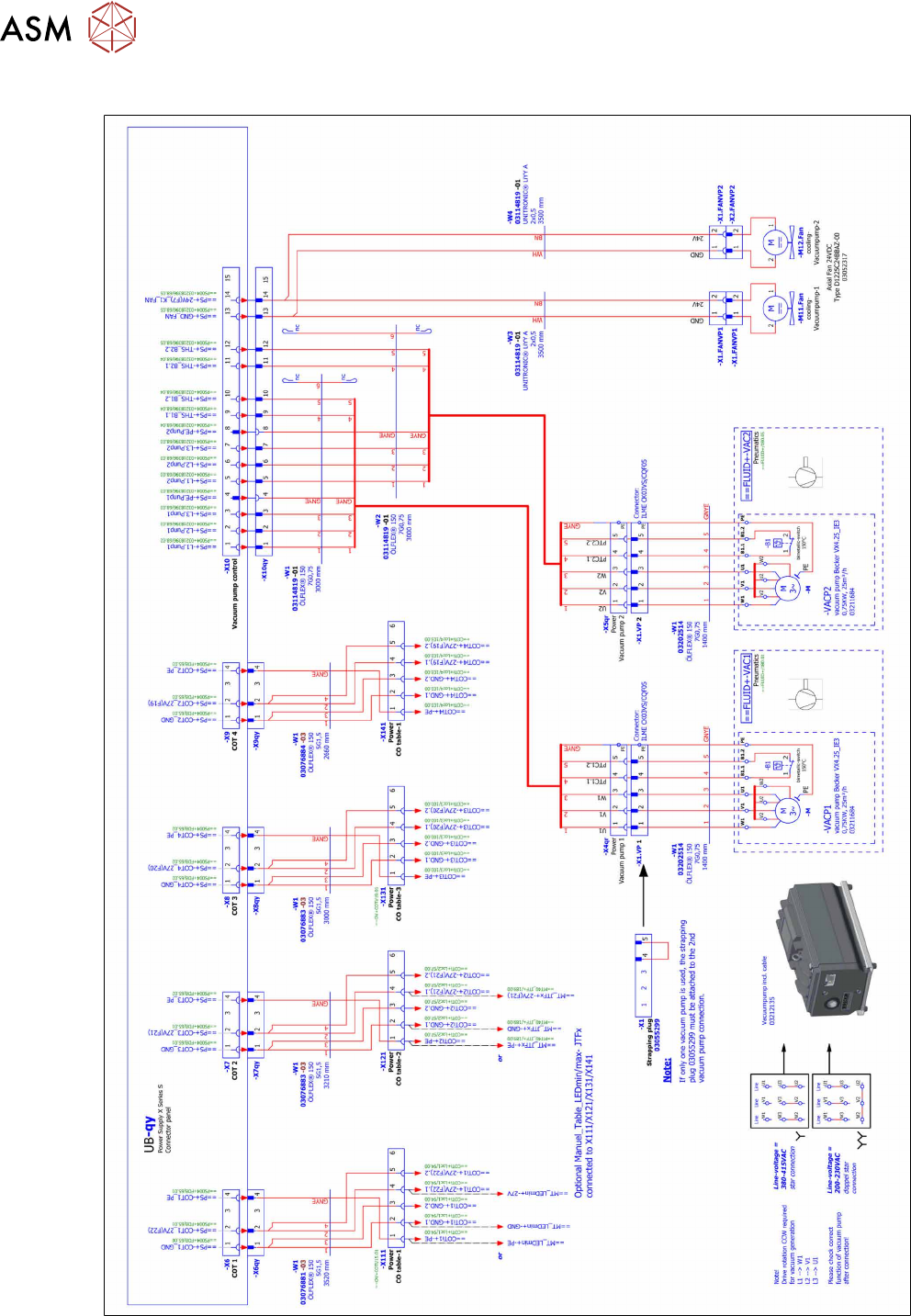
Detailed circuit diagram vacuum pump (new)
Fig.44: Detailed circuit diagram vacuum pump (new)
3 Installation
3.5 Installing the vacuum pump
Assembly Instructions / Montageanleitung SIPLACE X-Series S (from/ab Hxxxx) Option Vacuum Pump 02/2021 153
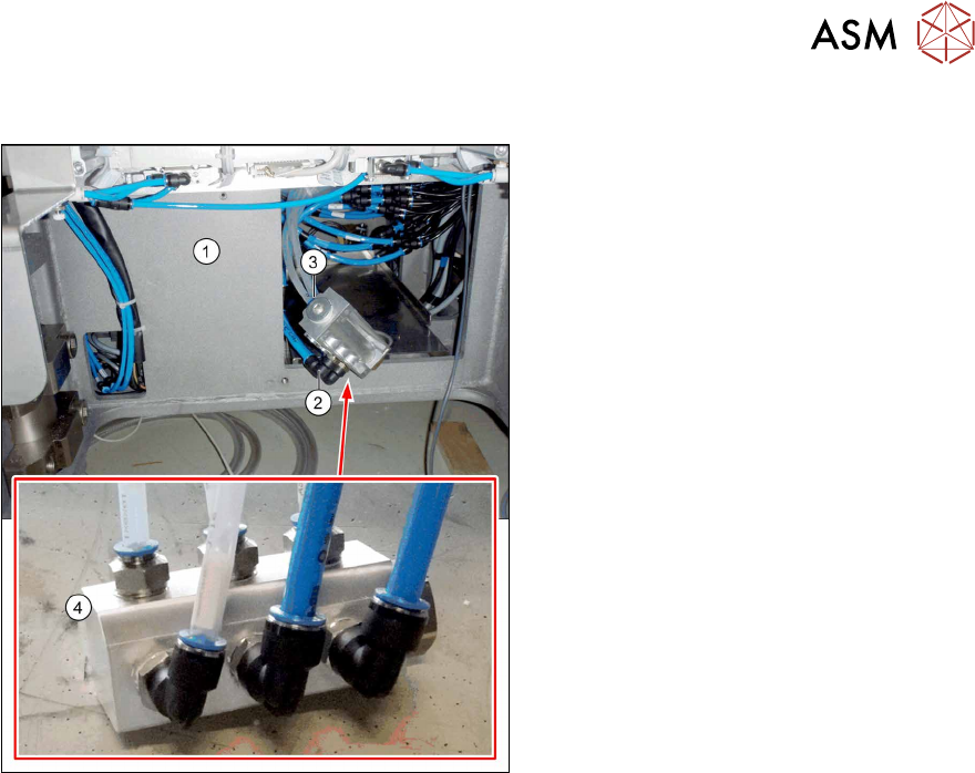
3.5.5 Preparing the vacuum distributor
Fig.45: Vacuum distributor without pump
► Pull the tube that has been disconnec-
ted from the proportional controller
back to the vacuum pump installation
location and connect it to the vacuum
distributor(4)
.
► Pull the transparent vacuum hoses (two
per gantry) that belong to the gantry to
be converted out of the machine base.
The vacuum hoses in the machine
have their maximum length.
► Shorten the two vacuum hoses to the
length required to connect them to the
vacuum distributor, which will be run in-
side the machine base at(1)
.
► Mark the vacuum hoses with the relev-
ant gantry number.
► Connect the size 12 PUN hose(2) and
the vacuum hoses(3)
to the vacuum
distributor.
► Perform the above mentioned tasks for all gantries to be converted.
► Fasten the vacuum hoses for the unconverted gantries with a cable tie and push these hoses
upwards in the machine base, to make room for installation of the pump.