00198599-02_AI_Vacuumpump_X-Series-S-from-Hxxxx_DE_EN.pdf - 第159页
3 Installation 3.5 Installing the vacuum pump Assembly Instructions / Montageanleitung SIPLACE X-Series S (from/ab Hxxxx) Option Vacuum Pump 02/2021 159 3.5.8 Installing the air box with exhaust air duct Fig.59: Air box…
3 Installation
3.5 Installing the vacuum pump
158 Assembly Instructions / Montageanleitung SIPLACE X-Series S (from/ab Hxxxx) Option Vacuum Pump 02/2021
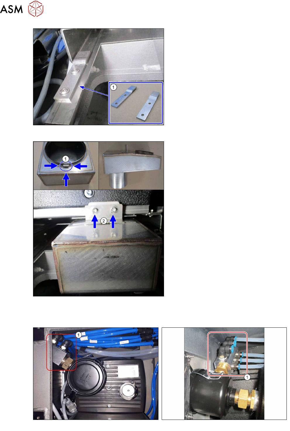
Fig.55: Fixing the vacuum pump in place
► Fix the vacuum pump with the two
fastenings(1)
[03224407‑xx].
Fig.56: Fixing the exhaust duct into place
► Hook(1) the exhaust duct [03223353‑xx]
into place and fix this with two screws(2)
(M5x8).
► Make sure that the vacuum pump is reli-
ably fixed into place. Make sure that the
vacuum pump does not vibrate.
3.5.7 Connecting the vacuum distributor to the pump
Fig.57: Vacuum distributor (old vacuum pump)
Fig.58: Vacuum distributor (new vacuum pump)
► Screw the vacuum distributor (1) to the vacuum pump filter (size 36 fork wrench).
3 Installation
3.5 Installing the vacuum pump
Assembly Instructions / Montageanleitung SIPLACE X-Series S (from/ab Hxxxx) Option Vacuum Pump 02/2021 159
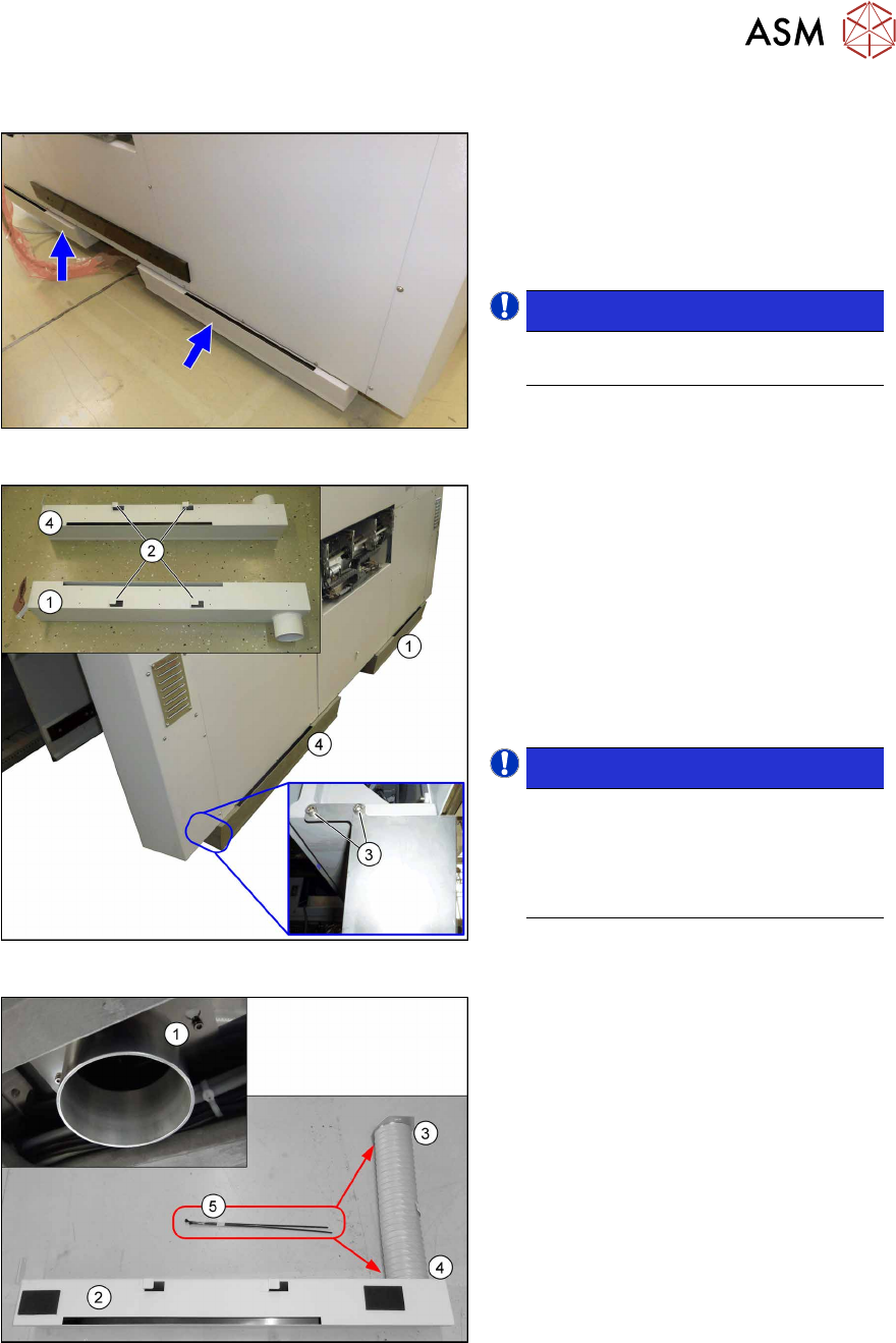
3.5.8 Installing the air box with exhaust air duct
Fig.59: Air box with duct
The "air box with felt left" and "air box with
felt right" are fitted to the bottom of the
machine and exhaust air hoses connect
them to the exhaust ducts of the vacuum
pumps.
One air box is installed per vacuum pump.
NOTICE!
The installation at location 1 and 4 is
identical.
.
Fig.60: Air box installation
1. Air box location 1
2. Hooks at the air boxes
3. Fastening screws
4. Air box location 4
► Hook the air box (using the hooks
provided) to the machine frame and fix
it in place with the two fastening
screws.
NOTICE!
Assignment of hoses
The short tube belongs to location4,
the long tube belongs to location1.
Use cable ties to fasten the tube to the
air box and the flange.
.
Fig.61: Exhaust air duct installation
1. Exhaust duct for vacuum pump
2. Air box
3. Tube end with flange, pre-assembled
with tube clamp – to the vacuum pump
4. Tube end without flange – to the air box
5. Cable ties W=4.8mm L=360mm
TYB-28M
► Fix the tube end with flange at the exhaust duct for the vacuum pump from below.
► Fix the tube end without flange at the air box.
3 Installation
3.5 Installing the vacuum pump
160 Assembly Instructions / Montageanleitung SIPLACE X-Series S (from/ab Hxxxx) Option Vacuum Pump 02/2021
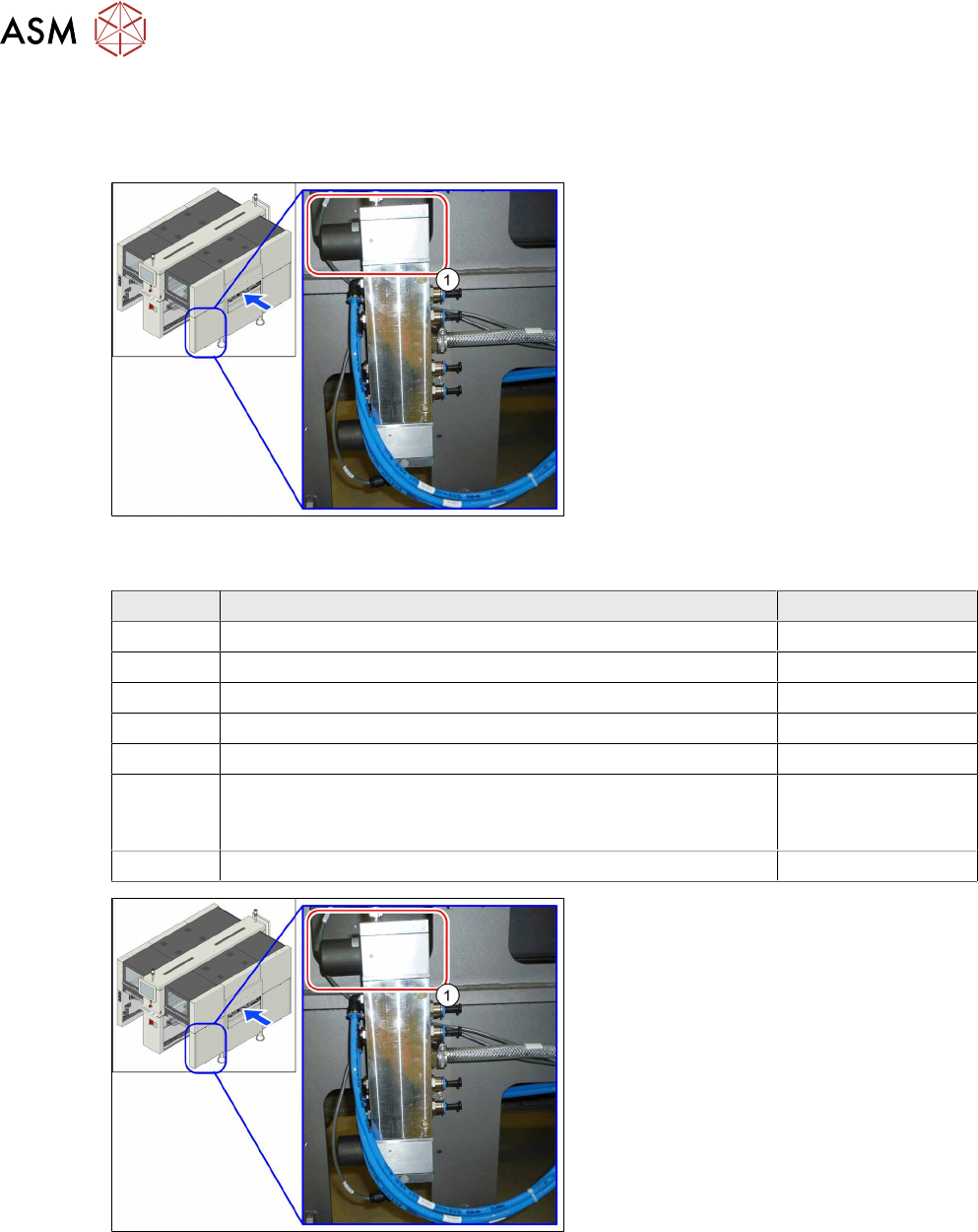
3.5.9 Connecting and running tubes
For more information about the proportional controller, refer to section
7.4.1
"Replacing the proportional controller (pressure control valve) (location 4)" [}186].
Fig.62: Proportional controller at location 4 (already without
hoses here, with dummy plugs)
Tasks on the proportional controller
Machines that are delivered with a vacuum
pump do not have the upper proportional
controller (1)
. A cover cap is fitted instead.
If the machine is to be converted to com-
pressed air operation, the proportional con-
troller must be retrofitted. The following
spare parts are required for this:
Quantity Designation Item no.
1 Proportional controller (pressure control valve) 03065425‑xx
1 O-Ring ID10 X 1.0 - NBR70 03031296‑xx
1 O-Ring ID20 X 1.0 - NBR70 03146099‑xx
1 O-Ring ID25 X 1.0 - NBR70 03146100‑xx
1 Sealing adapter plate proportional controller 03083211‑xx
1 Adapter plate top
or
Adapter plate bottom
03136076‑xx
or
03138952‑xx
5 ISO 10642 - M4x14-A2-70 03091400‑xx
Fig.63: Proportional controller (already without tubes here,
with dummy plugs)
We always recommend connecting the
tubes for a specific placement area one after
another to the vacuum pump. If you are con-
verting multiple gantries, disconnect/recon-
nect the tubes for one gantry at a time, to
prevent unintentional confusion of gantry
tube assignment.
► Localize the tube for the gantry to be
converted at the proportional controller
distributor (location4) and disconnect
this tube.
► Close the opening with a dummy
plug(1)
.