00198599-02_AI_Vacuumpump_X-Series-S-from-Hxxxx_DE_EN.pdf - 第140页
3 Installation 3.4 Converting the SIPLACE C&P20x 140 Assembly Instructions / Montageanleitung SIPLACE X-Series S (from/ab Hxxxx) Option Vacuum Pump 02/2021 3.4.3.2 Fitting the aperture ring and vacuum cover (SIPLACE …
3 Installation
3.4 Converting the SIPLACE C&P20x
Assembly Instructions / Montageanleitung SIPLACE X-Series S (from/ab Hxxxx) Option Vacuum Pump 02/2021 139
Fig.17: Aperture ring with sealing disk
► When tightening the screws, carefully
take hold of the star near the segment
guidances and hold it on the star car-
rier.
► Make sure you do not damage the anti-
glare shield or the nozzles.
Fig.18: Aperture ring [03046344‑xx] (example of SIPLACE
C&P20A shown)
► Screw the aperture ring tight using the
DIN912-M3x10 screws. Make sure that
it is not distorted.
► Tighten the screws.
Torque:
SIPLACE C&P20A/M: 0.25Nm
SIPLACE C&P20P 1.3Nm
► Check whether the O-ring 42x2 NBR70
has been properly placed into the
groove on the aperture ring.
Fig.19: Cover [03046347‑xx] (example of SIPLACE
C&P20A shown)
► Screw the cover [03046347‑xx] hand-
tight onto the aperture ring.
See also
2 7.4.6.1 "Replacing the holding circuit/aperture ring" [}194]
3 Installation
3.4 Converting the SIPLACE C&P20x
140 Assembly Instructions / Montageanleitung SIPLACE X-Series S (from/ab Hxxxx) Option Vacuum Pump 02/2021
3.4.3.2 Fitting the aperture ring and vacuum cover (SIPLACE C&P20 P2)
Overview
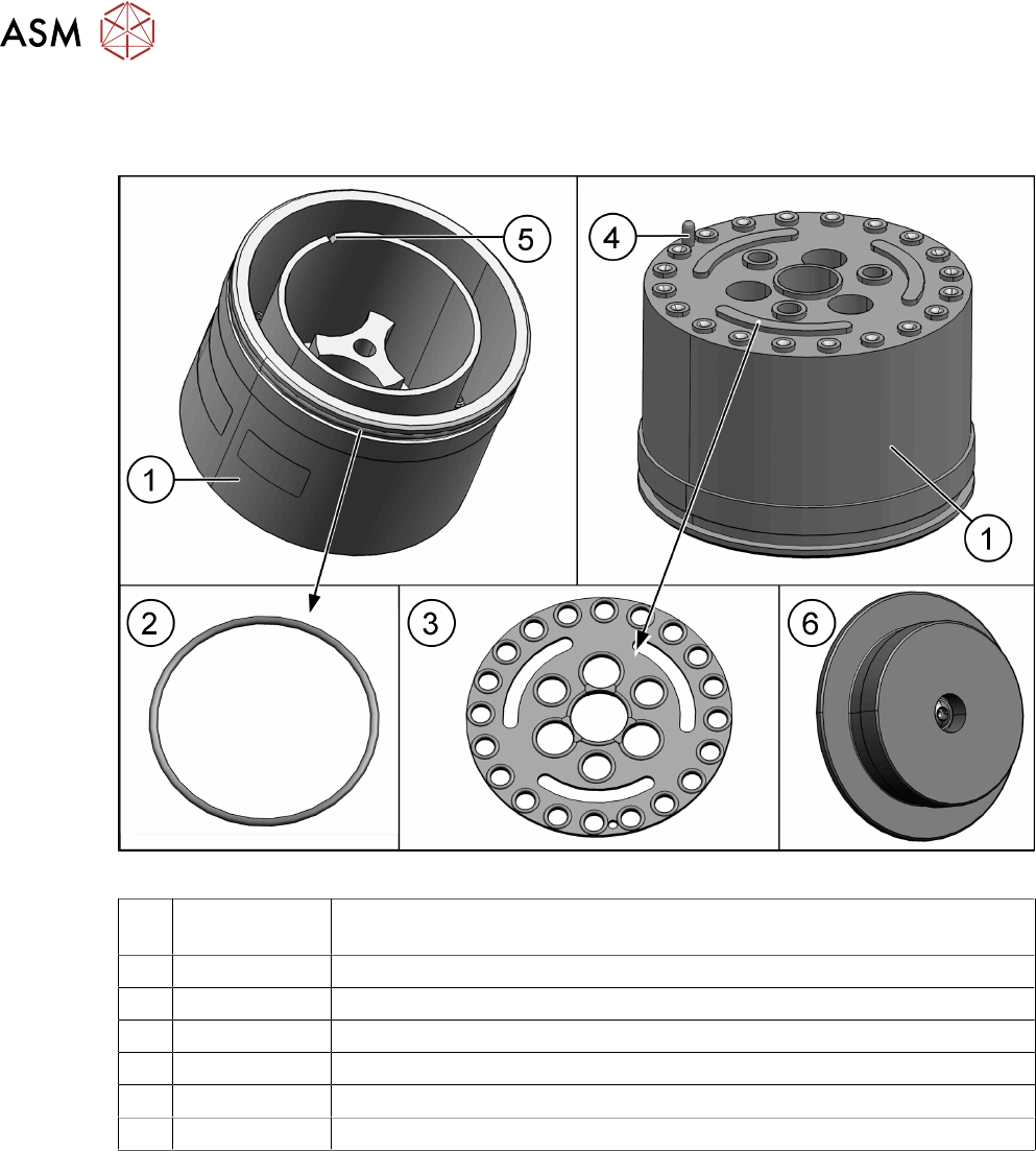
Fig.20: Aperture ring
1 03165750-xx Aperture ring assembly SIPLACE C&P20 P2 (including sealing disc and
cover)
2 03006234-xx O-Ring 40x1.5
3 03105638-xx Sealing disc C&P20P
4 --- Pins
5 --- Groove: this groove shows the position of the pin (4) for easier installation.
6 03165754-xx Cover assembly C&P20 P2
03110132‑xx Sealing gasket M4 (for cover)
3 Installation
3.4 Converting the SIPLACE C&P20x
Assembly Instructions / Montageanleitung SIPLACE X-Series S (from/ab Hxxxx) Option Vacuum Pump 02/2021 141
Installation
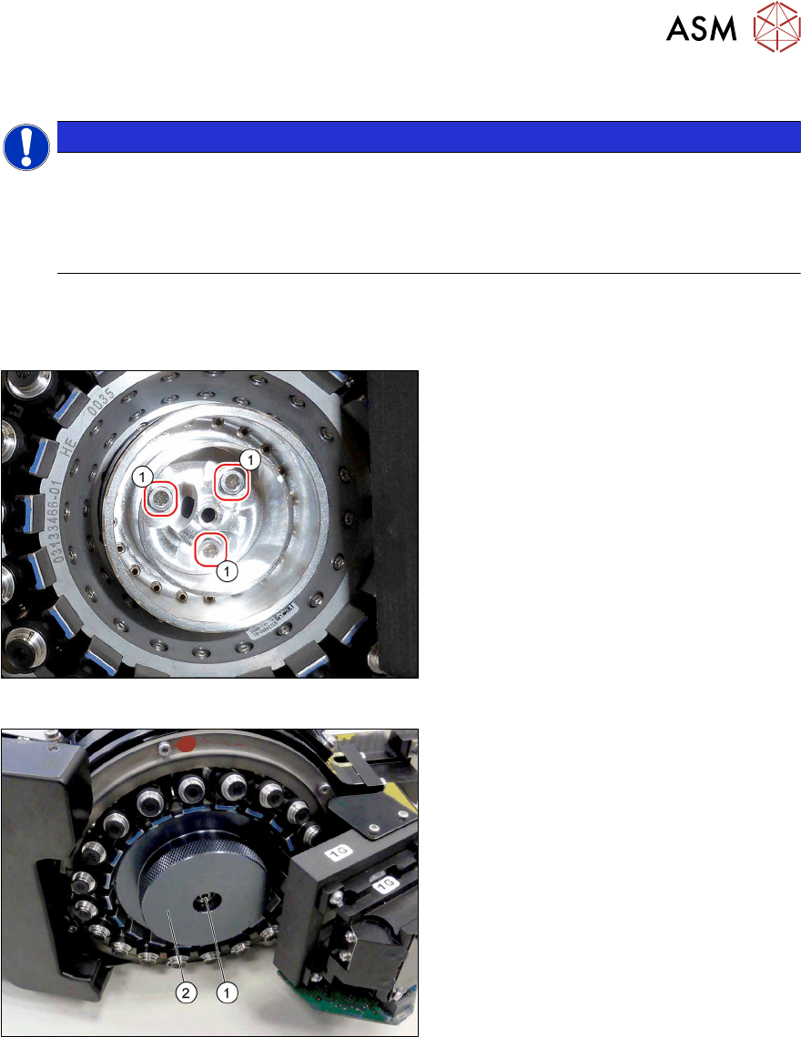
NOTICE
Aperture ring
Before inserting the aperture ring, make sure that the sealing disk has been positioned cor-
rectly (orientation) on the aperture ring.
When inserting the new aperture ring, make sure that the pin engages in the relevant hole
on the star carrier. The aperture ring should remain fixed by itself.
► When tightening the screws, carefully take hold of the star near the segment guidances and
hold it on the star carrier.
► Make sure you do not damage the anti-glare shield or the nozzles.
Fig.21: Aperture ring
► Fix the aperture ring into place with the
screws(1)
DIN912-M3x10 (1.3Nm).
Make sure that it is not distorted.
► Check whether the O-ring has been
properly placed into the groove on the
aperture ring.
Fig.22: Fitting the cover
► Fit the cover(2) and fix with a screw(1)
(TX10, M4x14, 1.3Nm).
See also
2 7.4.7.1 "Replacing the aperture ring/holding circuit/sealing disc" [}201]