00198599-02_AI_Vacuumpump_X-Series-S-from-Hxxxx_DE_EN.pdf - 第133页
3 Installation 3.3 Converting the gantries Assembly Instructions / Montageanleitung SIPLACE X-Series S (from/ab Hxxxx) Option Vacuum Pump 02/2021 133 3.3 Converting the gantries For conversion of the gantries to vacuum o…
3 Installation
3.2 Preparing the machine
132 Assembly Instructions / Montageanleitung SIPLACE X-Series S (from/ab Hxxxx) Option Vacuum Pump 02/2021
3.2 Preparing the machine
Before installing the pump, make sure that locations 1 to 4 are accessible.
► Undock the component trolleys from the relevant locations.
► Switch off the machine, disconnect it from the power supply and secure it to prevent
unauthorized reactivation.
1.2 "Preparatory work..." [}115]
CAUTION
Switch off the compressed air supply
The compressed air supply must always be switched off for all work on the pneumatic sys-
tem.
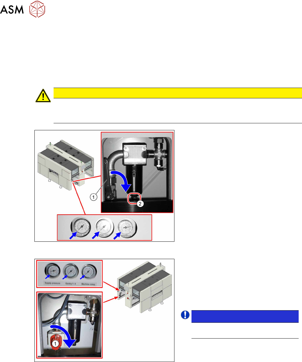
Fig.4: Disabling the compressed air supply (version 1)
Version 1:
► Push the lever (1) for the compressed
air supply down until it is positioned ho-
rizontally.
► Open the screw (2) on the inlet filter to
vent the system. Hold a cloth under-
neath to capture any escaping liquid.
Fig.5: Shutting off the compressed air supply (version 2)
Version 2:
► Push the switch (1) for the compressed
air supply by 90 degrees, until it is posi-
tioned horizontally.
► All pressure gauges must be set to
zero.
NOTICE!
Venting is performed automatically
in this version.
.
► Dismantle the waste tape chute.
7.4.5 "Replacing the waste tape slide" [}193]
► Dismantle the cover plate for the vacuum pump installation.
3 Installation
3.3 Converting the gantries
Assembly Instructions / Montageanleitung SIPLACE X-Series S (from/ab Hxxxx) Option Vacuum Pump 02/2021 133
3.3 Converting the gantries
For conversion of the gantries to vacuum operation, you require the following upgrade kits:
●
1x upgrade kit vacuum X4i rotated [03075306‑xx] (gantry2 and4)
only for X4i S, one per gantry.
●
1x upgrade kit vacuum X-Series R10 [03075305] (gantries1 and3)
one per gantry on an X4i S
one per gantry on an X4S, X3S, X2S.
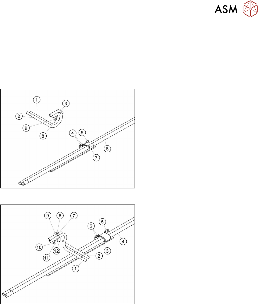
Fig.6: Upgrade kit vacuum X-Series R10
1. Tube for vacuum connection 1
2. Tube for vacuum connection 2
3. Clamping piece
4. Two screws (ISO7380-2 M3x6-A2-70)
(Loctite241)
5. Stabilizer damped
6. Duo hose
7. Foam rubber
8. One screw ISO7093-1-3-200HV-A2
9. One screw ISO4762-M3x35-A2-70
(Loctite241)
Fig.7: Upgrade kit vacuum X4i turned
1. Tube for vacuum connection 1 turned
2. Tube for vacuum connection 2 turned
3. Foam rubber
4. Duo hose
5. Stabilizer
6. Two screws ISO7380-2M3x6-A2-70
(Loctite241)
7. One screw ISO7089-2.5-200HV-A2
8. One screw ISO4762-M3x18-A2-70
(Loctite241)
9. Clamping piece
10. One screw ISO4762-M3x14-A2-70
(Loctite241)
11. One screw ISO7093-1-3-200HV-A2
12. Holder
The following section illustrates the conversion of a distributor for placement heads to vacuum
pump operation, using the example of gantry1/3.
See also
2 7.3 "Error message: 30356 Vacuum in holding circuit too low" [}183]
3 Installation
3.3 Converting the gantries
134 Assembly Instructions / Montageanleitung SIPLACE X-Series S (from/ab Hxxxx) Option Vacuum Pump 02/2021
3.3.1 Connecting the vacuum hoses to the placement head vacuum distributor
Also observe section 7.4.4 "Handling the hose unlocking tool" [}192].
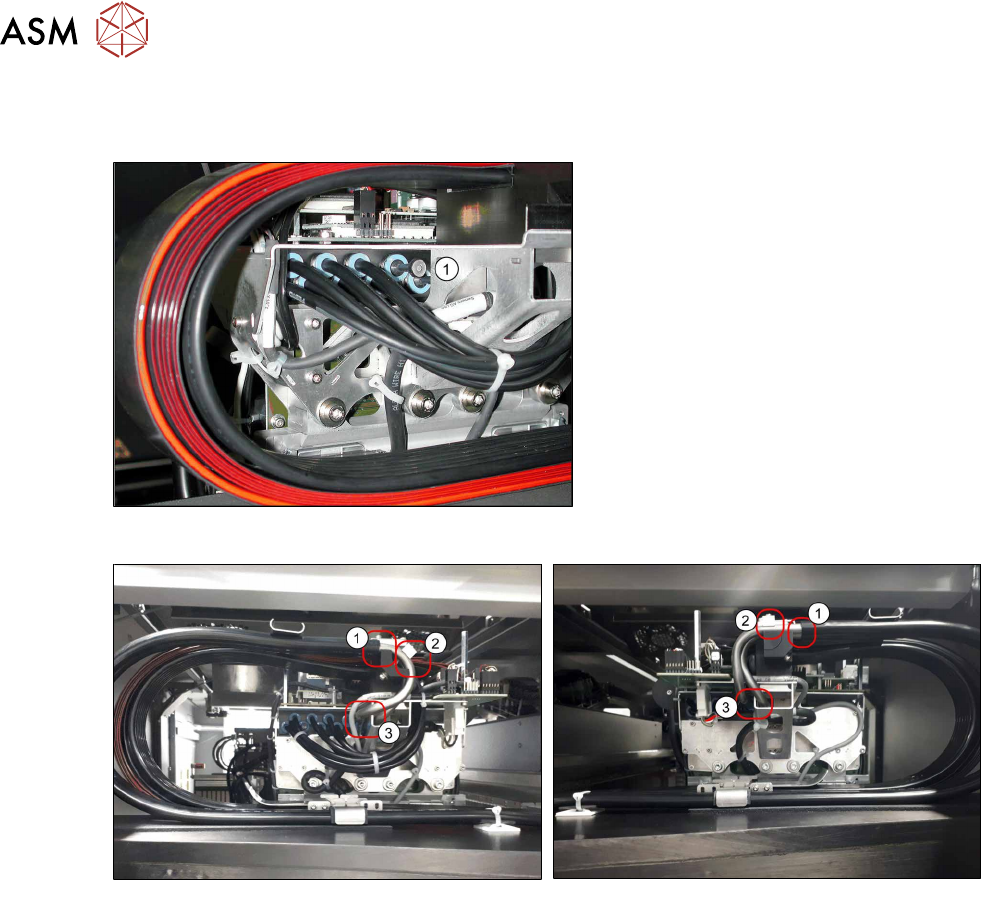
Fig.8: Dummy plugs
► Use the unlocking tool for Q8 to
remove both dummy plugs from the
vacuum distributor(1)
at all gantries to
be converted.
Fig.9: Standard gantry
Fig.10: Rotated gantry
► Attach the vacuum hoses to the two tubes for vacuum connection 1 und 2(1).
► Connect the two tubes to the placement head vacuum distributor(3).
► Fasten the vacuum connection tubes1 and2 using the clamping piece(2), with the help of an
M3x30mm screw and a washer (Loctite 241
).