00198599-02_AI_Vacuumpump_X-Series-S-from-Hxxxx_DE_EN.pdf - 第193页
7 Appendix 7.4 Excerpts from the service manual Assembly Instructions / Montageanleitung SIPLACE X-Series S (from/ab Hxxxx) Option Vacuum Pump 02/2021 193 7.4.5 Replacing the waste tape slide Parts, equipment and tools ●…
7 Appendix
7.4 Excerpts from the service manual
192 Assembly Instructions / Montageanleitung SIPLACE X-Series S (from/ab Hxxxx) Option Vacuum Pump 02/2021
7.4.3 Venting compressed air at the cutter
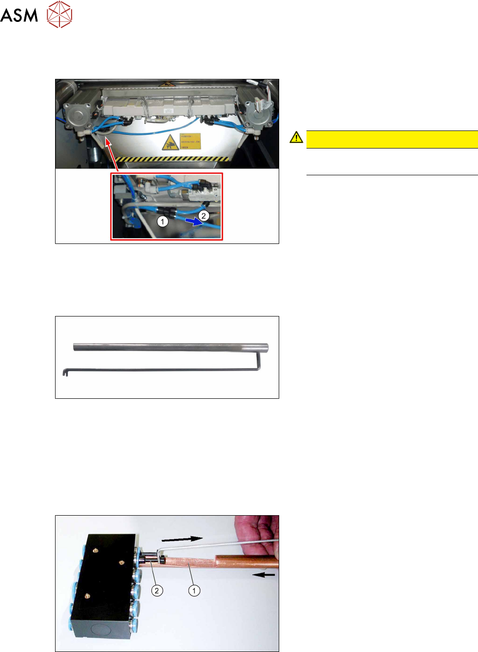
► Switch off the compressed air supply
Fig.102: Disconnecting the hose
► Carefully pull one of the two small
hoses(2)
of the Y-piece(1).
This enables any compressed air still
present in the system to be released.
CAUTION!
Risk of injury
The hoses could still be pressurized.
.
7.4.4 Handling the hose unlocking tool
Equipment and tools
Fig.103: Unlocking tool
●
Tool set vacuum connection X-Series
(unlocking tool) [03051867‑xx]
Consists of:
– Hose unlocking tool [03047090-xx]
– Unlocking tool for QSC-10H
[03051853-xx]
Usage
► Switch off the compressed air supply
Due to the poor access to the pneumatic distributor, we recommend using the unlocking tool.
With the help of the hose unlocking tool, you can open the unlocking ring for the compressed air
connection. This enables you to remove both the hoses and the blanking plugs (additional tool "Un-
locking tool for QSC-10H" [03051853-xx]).
Fig.104: Handling the unlocking tool
► Use the pipe-shaped tool (1) to open
the unlocking ring (blue here).
► Carefully pull the hose or the blanking
plug(2)
out of the compressed air con-
nection.
7 Appendix
7.4 Excerpts from the service manual
Assembly Instructions / Montageanleitung SIPLACE X-Series S (from/ab Hxxxx) Option Vacuum Pump 02/2021 193
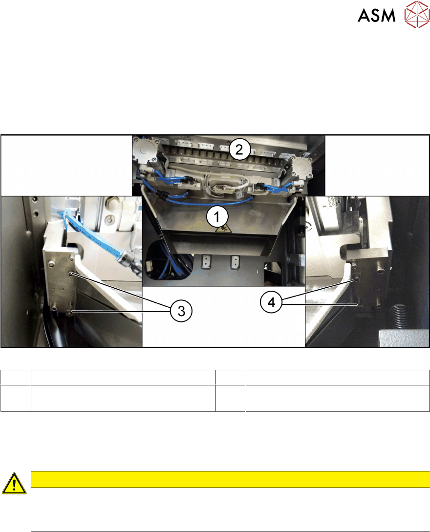
7.4.5 Replacing the waste tape slide
Parts, equipment and tools
●
Used tape chute complete [03067460-xx]
●
Allen key set
Overview
Fig.105: Waste tape slide
1 Waste tape slide 2 COT insert
3 Fastening screw for used tape chute, left 4 Fastening screw for used tape chute,
right
Removal
► Remove the screws fastening the used tape chute.
► Take the used tape chute down and out of the machine.
CAUTION
Risk of cutting
The cutter is located under the tape channel. The blades there have very sharp edges.
► Do not reach into the cutter and make sure that it is never freely accessible.
Installation
► Follow the removal instructions in reverse order for installation.
7 Appendix
7.4 Excerpts from the service manual
194 Assembly Instructions / Montageanleitung SIPLACE X-Series S (from/ab Hxxxx) Option Vacuum Pump 02/2021
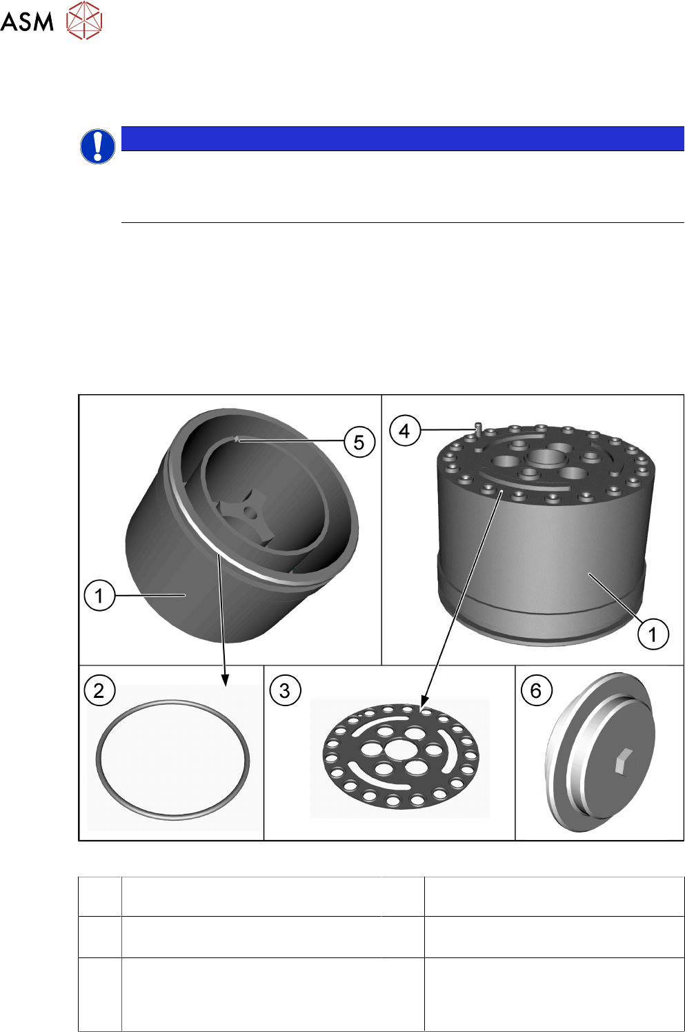
7.4.6 SIPLACE C&P20 A/M/P
7.4.6.1 Replacing the holding circuit/aperture ring
NOTICE
Description example
The replacement of the holding circuit (Venturi mode) and aperture ring (vacuum pump
mode) is identical. The following section describes the replacement, using the example of
the aperture ring. Any relevant differences will be mentioned explicitly.
Parts
●
Holding circuit vacuum unit [03005123Sxx]
or
Orifice plate complete for SIPLACE C&P20P [03116883Sxx] (replaces:[03108716‑xx])
●
O-ring, if needed:
Vacuum mode (aperture ring): O-ring 40x1.5 [03006234-xx]
Compressed air mode (holding circuit): O-ring 50x1.5 [03046689-xx]
Overview
Fig.106: Aperture ring
1 Orifice plate, preassembled for
SIPLACE C&P20P [03116952‑xx])
2 O-ring [03006234-xx]
3 Sealing disc for SIPLACE C&P20P
[03105638-xx]
4 Pins
The pin is located at segment 16
5 Groove – this groove shows the position
of the pin (4)
for easier installation.
6 Cover assembly for SIPLACE C&P20P
[03116882‑xx]
Not shown: sealing gasket U - M4 (for
cover) [03110132‑xx]