00198599-02_AI_Vacuumpump_X-Series-S-from-Hxxxx_DE_EN.pdf - 第135页
3 Installation 3.3 Converting the gantries Assembly Instructions / Montageanleitung SIPLACE X-Series S (from/ab Hxxxx) Option Vacuum Pump 02/2021 135 3.3.2 Connecting the tubes and hoses Fig.11: Overview of tube connect…
3 Installation
3.3 Converting the gantries
134 Assembly Instructions / Montageanleitung SIPLACE X-Series S (from/ab Hxxxx) Option Vacuum Pump 02/2021
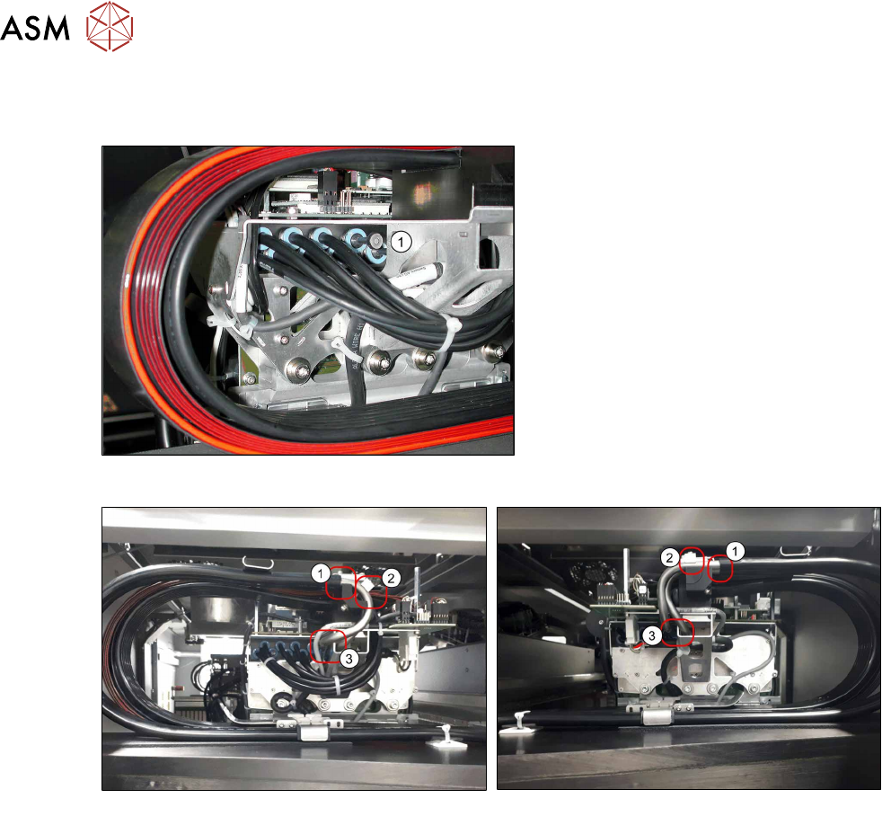
3.3.1 Connecting the vacuum hoses to the placement head vacuum distributor
Also observe section 7.4.4 "Handling the hose unlocking tool" [}192].
Fig.8: Dummy plugs
► Use the unlocking tool for Q8 to
remove both dummy plugs from the
vacuum distributor(1)
at all gantries to
be converted.
Fig.9: Standard gantry
Fig.10: Rotated gantry
► Attach the vacuum hoses to the two tubes for vacuum connection 1 und 2(1).
► Connect the two tubes to the placement head vacuum distributor(3).
► Fasten the vacuum connection tubes1 and2 using the clamping piece(2), with the help of an
M3x30mm screw and a washer (Loctite 241
).
3 Installation
3.3 Converting the gantries
Assembly Instructions / Montageanleitung SIPLACE X-Series S (from/ab Hxxxx) Option Vacuum Pump 02/2021 135
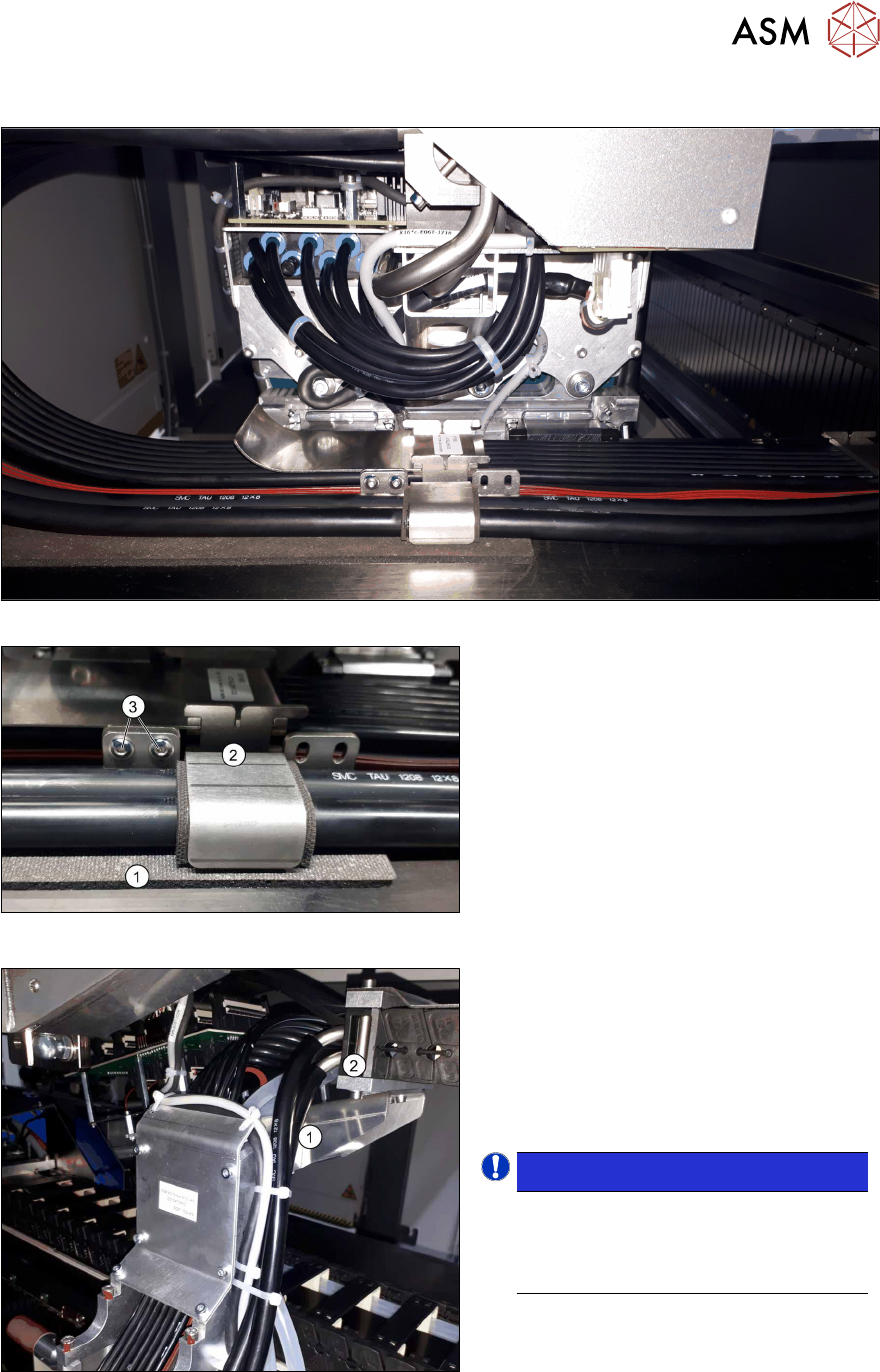
3.3.2 Connecting the tubes and hoses
Fig.11: Overview of tube connections
Fig.12: Fastening the foam rubber and the downholder
► Fasten the foam rubber(1) as illus-
trated.
► Fit the downholder(2) using two
screws(3)
(Loctite 241).
Fasten the downholder at the opposite
gantry in the same way so that the
downholder is always positioned as
near as possible towards the inside of
the gantry.
Fig.13: Running and fastening the tubes
► Run the two new tubes to the trailing
cable at the gantry root.
► Run the tubes next to the guide plate
and upwards(1)
.
There may be differences here, due to
the different variants of the gantry trail-
ing cable.
NOTICE!
Use cable ties to fasten the tubes or
hoses where necessary.
Make sure that you do not restrict the
tube or hose width with the cable tie.
.
► Connect the two transparent hoses to
the connection(2).
See also
2 7.3 "Error message: 30356 Vacuum in holding circuit too low" [}183]
3 Installation
3.4 Converting the SIPLACE C&P20x
136 Assembly Instructions / Montageanleitung SIPLACE X-Series S (from/ab Hxxxx) Option Vacuum Pump 02/2021
3.4 Converting the SIPLACE C&P20x
●
Conversion kit "Aperture ring assembly C&P20 P" [03116883Sxx]
NOTICE
Restrictions for SIPLACE Twin or SIPLACE CPP on the gantry to be converted
The SIPLACE Twin and the SIPLACE CPP are not compatible with vacuum pump opera-
tion. Do not convert the pneumatic supply for the gantry affected to vacuum mode. If the
compressed air supply for this head is converted to vacuum operation, the return cylinder
will be unable to move out and the Z axis will remain in its top position.
CAUTION
Conversion from SIPLACE C&P20x to SIPLACE Twin or SIPLACE CPP
If you need to convert a gantry from SIPLACE C&P20x to SIPLACE Twin/CPP, you must
re-establish the original compressed air supply for this gantry. Conversion reversal must be
performed on all assemblies for this gantry. Partial conversion of the pneumatic unit, for
example, involving disconnection of the gantry tubes (additional vacuum tubes) during com-
pressed air operations, can lead to serious placement machine malfunctions.
CAUTION
Conversion from SIPLACE Twin to SIPLACE C&P20x with vacuum operation
If you need to convert a gantry from SIPLACE Twin to SIPLACE C&P20x with vacuum op-
eration, you must retrofit the vacuum equipment for this gantry. If you operate a C&P20x
which has been converted for vacuum operation at a gantry with compressed air, this could
lead to serious damage to the placement head if the silicon hoses to the segments should
loosen.
Original state - C&P20x for compressed air operation
CAUTION
Preparatory work
After you have properly shut-down the operating system: turn the machine off at the main
switch and isolate it from the mains, before you perform any work to the machine. In addi-
tion, the compressed air supply must be turned off at the main valve of the compressed air
unit, in the machine base, and the compressed air lines must be bled by actuating the
needle valve on the compressed air unit. See also 1.2
"Preparatory work..." [}115].
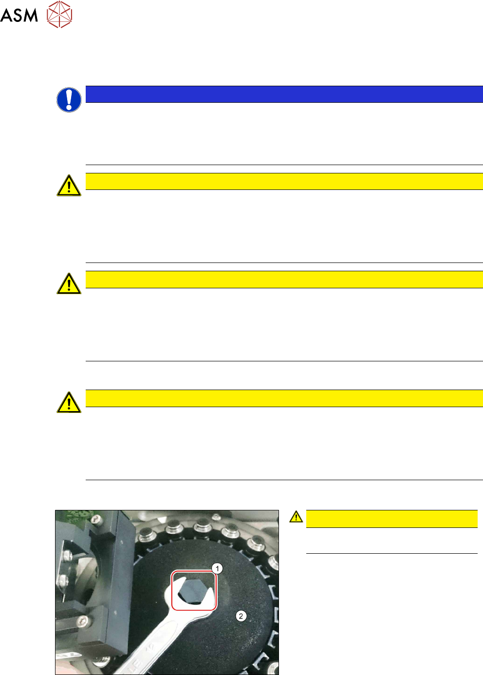
3.4.1 Removing the silencer
Fig.14: Silencer (example of SIPLACE C&P20P shown)
CAUTION!
Make sure that you do not damage or
contaminate the camera lens system.
.
► Remove the screw (1) fastening the si-
lencer.
► Carefully pull off the silencer(2).
► Make sure that you do not damage the
DP drives.
See also
2 7.4.6.2 "Replacing the silencer (Venturi mode only)" [}200]