00198599-02_AI_Vacuumpump_X-Series-S-from-Hxxxx_DE_EN.pdf - 第197页
7 Appendix 7.4 Excerpts from the service manual Assembly Instructions / Montageanleitung SIPLACE X-Series S (from/ab Hxxxx) Option Vacuum Pump 02/2021 197 Fig.110: Screws fastening the aperture ring ► Remove the three s…
7 Appendix
7.4 Excerpts from the service manual
196 Assembly Instructions / Montageanleitung SIPLACE X-Series S (from/ab Hxxxx) Option Vacuum Pump 02/2021
Torques in vacuum pump operation
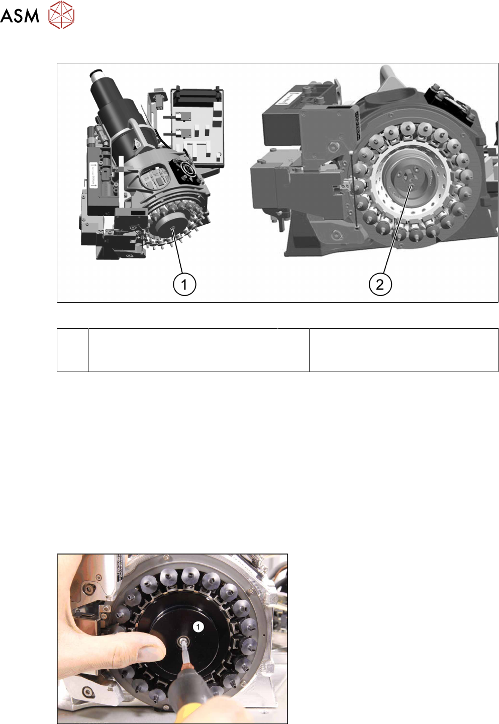
Fig.108: Cover and aperture ring
1 Cover
Fastening screw M3x14 (Allen key2.5)
Torque: hand-tight
2 Aperture ring
Three fastening screws M3x10
Torque: 1.3Nm
Torques in Venturi operation
Silencer
Special screw M3 (SW10)
Torque: hand-tight
Holding circuit
Three fastening screws M3x10 (Allen
key2.5)
Torque: 0.25Nm
Preparation
► Remove the head from the machine. For details about removing and fitting the placement
head, refer to the service manual for your machine.
Fit the head on the head mount [03056231‑xx].
► Make sure that the component sensor protective cap is fitted.
Removal
Fig.109: Dismantling the cover
► Remove the screw fastening the
cover(1)
and then take the cover off.
7 Appendix
7.4 Excerpts from the service manual
Assembly Instructions / Montageanleitung SIPLACE X-Series S (from/ab Hxxxx) Option Vacuum Pump 02/2021 197
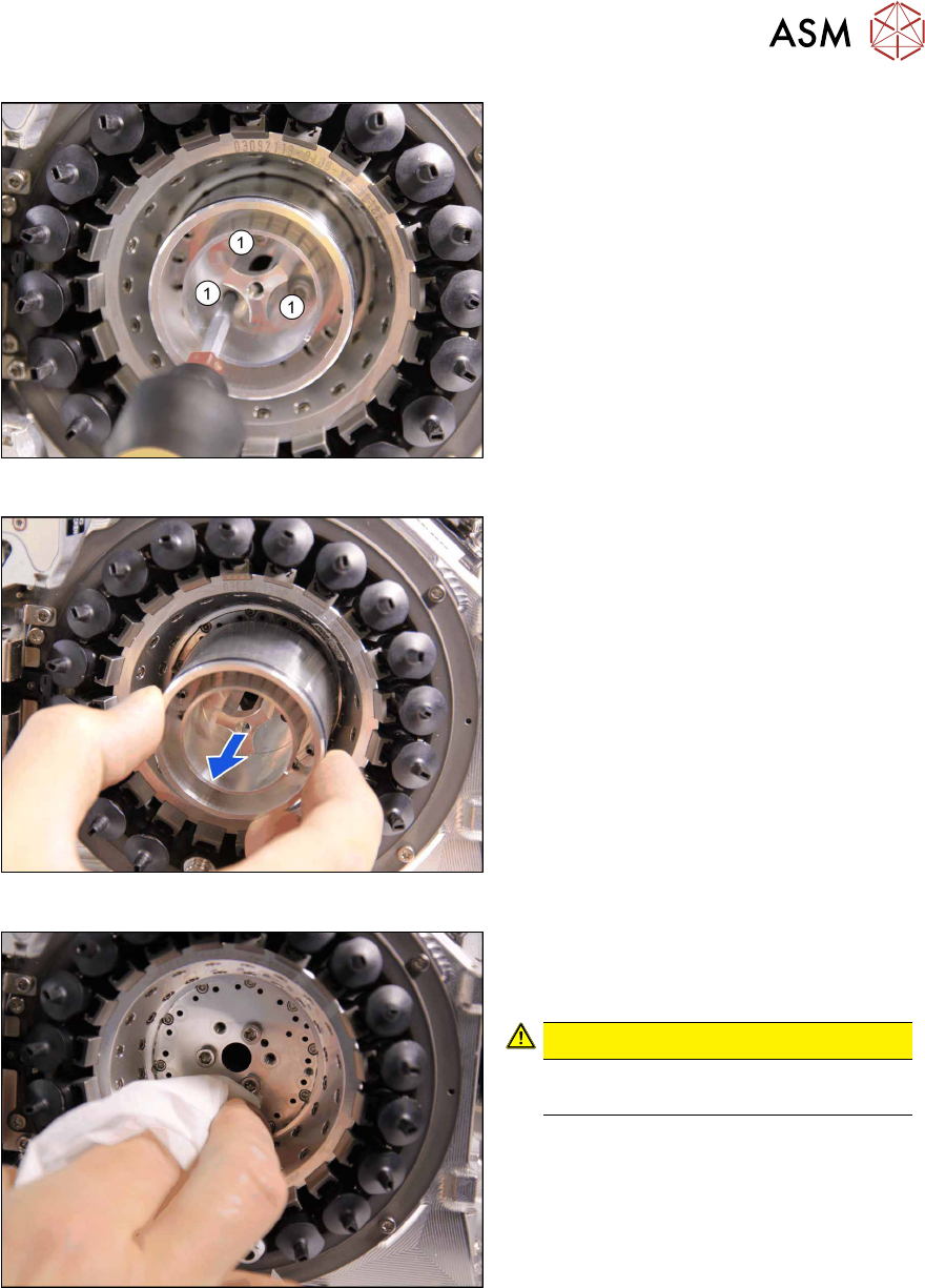
Fig.110: Screws fastening the aperture ring
► Remove the three screws(1) fastening
the aperture ring.
Fig.111: Removing the aperture ring
► Carefully lever the aperture ring off the
locating pins. Make sure that the O-ring
is not damaged.
Fig.112: Cleaning
► Clean the seat of the aperture ring with
a lint-free cleaning cloth, if required.
CAUTION!
Do not use compressed air for
cleaning!
.
7 Appendix
7.4 Excerpts from the service manual
198 Assembly Instructions / Montageanleitung SIPLACE X-Series S (from/ab Hxxxx) Option Vacuum Pump 02/2021
Installation
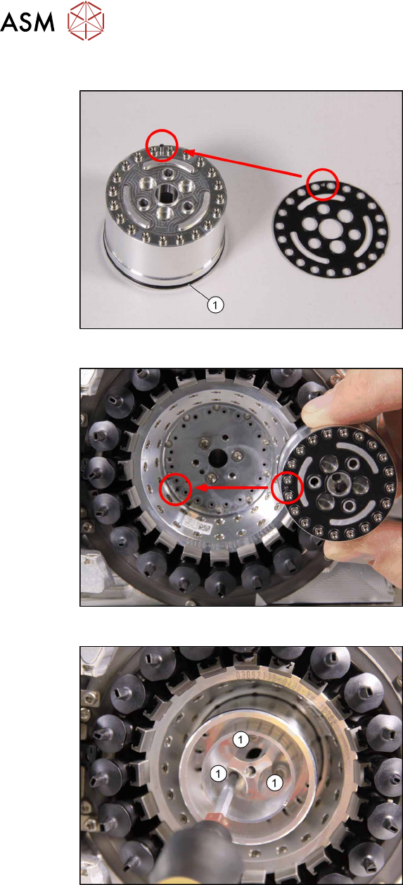
Fig.113: O‑Ring and sealing disc
► If the O-ring (1) is damaged, replace it
with a new one.
► Correctly position the sealing disc on
the aperture ring. Make sure all open-
ings are aligned.
Fig.114: Inserting the aperture ring
► Position the aperture ring (with sealing
disc) correctly onto the locating pins in
the star carrier.
Fig.115: Fastening the holding circuit/aperture ring
► Venturi operation with holding cir-
cuit only: Fix the holding circuit into
place with the three fastening screws.
Tighten the screws to a torque of 0.25
Ncm.
► Vacuum pump operation with aper-
ture ring only: Fix the aperture ring
with the three fastening screws.
Tighten the screws to a torque of 1.3
Ncm.