00198599-02_AI_Vacuumpump_X-Series-S-from-Hxxxx_DE_EN.pdf - 第163页
3 Installation 3.5 Installing the vacuum pump Assembly Instructions / Montageanleitung SIPLACE X-Series S (from/ab Hxxxx) Option Vacuum Pump 02/2021 163 3.5.11 Installing the fan plate Fig.68: Connecting the fan cable (…
3 Installation
3.5 Installing the vacuum pump
162 Assembly Instructions / Montageanleitung SIPLACE X-Series S (from/ab Hxxxx) Option Vacuum Pump 02/2021
3.5.10 Checking the direction of pump operation
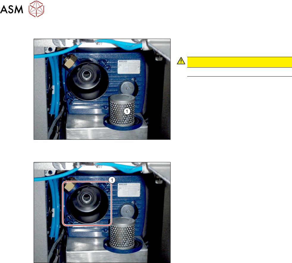
Fig.66: Removing the filter (example of old vacuum pump
shown)
► Open the brackets holding the filter
cover and remove the filter(1)
.
CAUTION!
Do not reach into the pump!
.
► Switch the machine on at the main
switch. The vacuum pump must also
switch itself on, although this might not
occur immediately after the machine is
switched on.
Fig.67: Suction opening (example of old vacuum pump
shown)
► Hold a hand or sheet of paper in front
of the suction opening of the pump(1).
ð The pump must be sucking air into
the machine!
► If the pump is running in the wrong direction, disconnect the entire system from the voltage
supply. Unplug the vacuum pump from the power.
– If both connections for the vacuum pump show the same effect, rewire the network cable
connection in the connection unit (exchange two phases - 24 Volt in the Mine Mad BN
Lock plug).
– If only one vacuum pump is running incorrectly, rewire at the relevant vacuum pump (ex-
change two phases - 24 Volt in the Mini Mad BN Lock plug).
► Return the filter.
► Check the connections for air-tightness. Make sure that they are not sucking in air incorrectly.
3 Installation
3.5 Installing the vacuum pump
Assembly Instructions / Montageanleitung SIPLACE X-Series S (from/ab Hxxxx) Option Vacuum Pump 02/2021 163
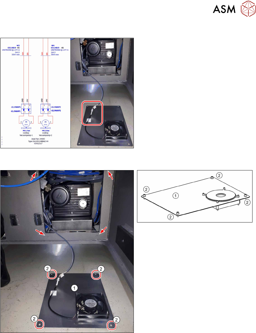
3.5.11 Installing the fan plate
Fig.68: Connecting the fan cable (example of old vacuum
pump shown)
► Plug the fan cable W3 into connector
X1 FANVP1 and the fan cable W4 into
connector X1 FanVP2 at the fan.
► Secure the cable using a cable tie.
Fig.69: Holes drilled for screws to fasten the fan plate
(example of old vacuum pump shown)
Fig.70: Fan plate
The cooling plate(1) is fitted after all other
work has been completed.
► Fasten the fan plate(1) [03098622‑xx]
from the outside with four screws
[03007765‑xx] (M6x16) and wash-
ers(2)
[03022691‑xx] (M6).
3 Installation
3.5 Installing the vacuum pump
164 Assembly Instructions / Montageanleitung SIPLACE X-Series S (from/ab Hxxxx) Option Vacuum Pump 02/2021
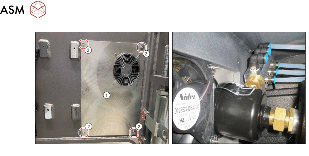
Fig.71: Cooling plate, fitted
Fig.72: Pneumatic distributor and fan
Fan function test
Perform a fan function test as follows:
► Switch the placement machine on at the main switch. The vacuum pump must also switch it-
self on, although this might not occur immediately after the machine is switched on.
► Check the direction of fan operation. The fan must blow air into the machine.
If the fan is running incorrectly, turn the 24Volt in the Mini Mad BN Lock connection.