00198599-02_AI_Vacuumpump_X-Series-S-from-Hxxxx_DE_EN.pdf - 第189页
7 Appendix 7.4 Excerpts from the service manual Assembly Instructions / Montageanleitung SIPLACE X-Series S (from/ab Hxxxx) Option Vacuum Pump 02/2021 189 Installation Follow the removal instructions in reverse order for…
7 Appendix
7.4 Excerpts from the service manual
188 Assembly Instructions / Montageanleitung SIPLACE X-Series S (from/ab Hxxxx) Option Vacuum Pump 02/2021
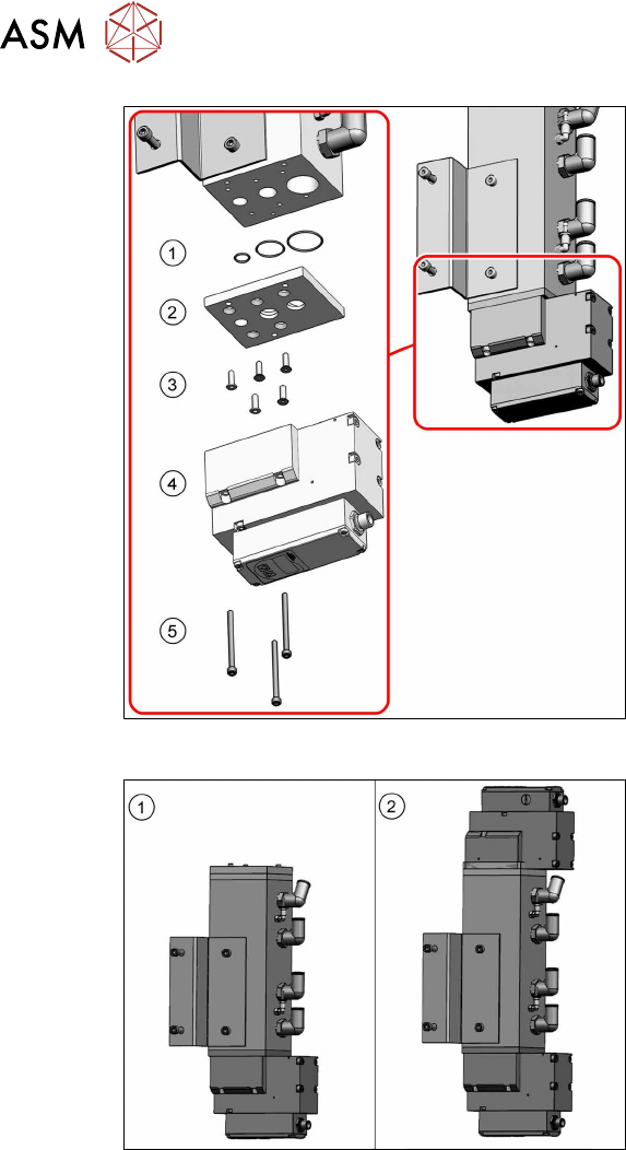
Fig.95: Overview proportional controller (version2)
Version 2:
1. 1x O-ring ID10 X 1.0 - NBR70
[03031296‑xx]
1x O-ring ID20 X 1.0 - NBR70
[03146099‑xx]
1x O-ring ID25 X 1.0 - NBR70
[03146100‑xx]
2. Adapter plate bottom [03138952‑xx]
3. 5x ISO10642-M4x14-A2-70
[03091400‑xx]
Torque: 2.5Nm
Loctite 241
4. 1x Proportional controller Sentronic-LP
[03152704‑xx]
5. 3x ISO4762-M4x55-A2-70
[03147182‑xx]
Torque: 2.0 – 2.5Nm
Loctite 241
Fig.96: Proportional controller configurations
Configurations
Depending on the configuration, there will be
one or two proportional controllers fitted.
1. One proportional controller (bottom)
Only one proportional controller is fit-
ted, if the machine is operated exclus-
ively with SIPLACE C&P20x in vacuum
mode.
2. Two proportional controllers (top and
bottom)
Two proportional controllers are re-
quired in all other cases (mixed head
mode or compressed air mode).
Removal
► Switch off the machine, disconnect it from the power supply and secure it to prevent
unauthorized reactivation.
1.2 "Preparatory work..." [}115]
► Switch off the compressed air supply and then disconnect the machine from the compressed
air supply.
► To do this, remove the screws fastening the side cover at location 4 and remove this cover.
► Unplug the electrical connection to the proportional controller.
► Remove the screws fastening the proportional controller and then remove the controller.
7 Appendix
7.4 Excerpts from the service manual
Assembly Instructions / Montageanleitung SIPLACE X-Series S (from/ab Hxxxx) Option Vacuum Pump 02/2021 189
Installation
Follow the removal instructions in reverse order for installation. Also observe the following instruc-
tions:
► Observe the instructions in section Sealing the Screwed Connections.
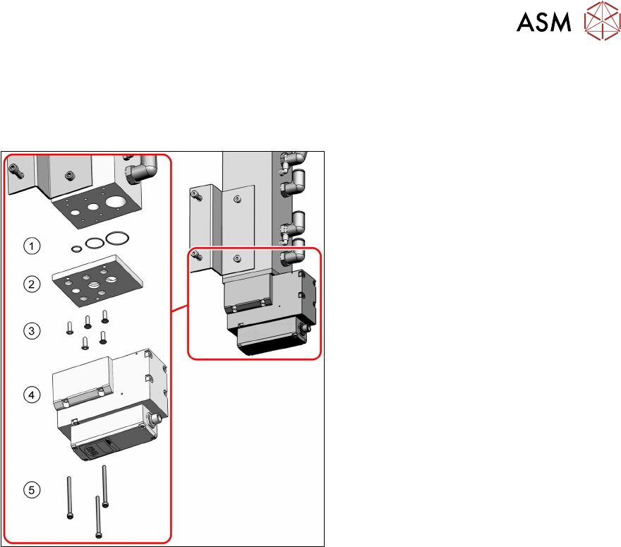
Fig.97: Overview proportional controller (version2)
► Clean the sealing rings(1)and the
adapter plate(2)
.
► Lightly grease the sealing rings with
Isoflex Topas NCA52 and insert these
again into the adapter plate.
► Fit the adapter plate with five fastening
screws(3)
(torque: 2.5Nm, Loc-
tite241).
► Fit the proportional controller(4) with
three fastening screws(5)
(torque of
2.0 to 2.5Nm, Loctite241).

7 Appendix
7.4 Excerpts from the service manual
190 Assembly Instructions / Montageanleitung SIPLACE X-Series S (from/ab Hxxxx) Option Vacuum Pump 02/2021
7.4.2 Replacing the pressure sensor [03108303-xx]
Parts, equipment and tools
●
Upgrade kit pressure sensor for vacuum C&P20P [03108457‑xx]
Overview
Fig.98: Pressure sensor
NOTICE!
The pressure sensor is only needed
when a vacuum pump and CPx heads
are installed.
In this case, the pressure sensor is es-
sential for operation of the placement
machine.
.
Fig.99: Pressure sensor on the gantry
1. Pressure sensor
2. Base adapter
The pressure sensor is located on the
vacuum distributor of the gantry and is con-
nected to the base (X8) adapter.