00198599-02_AI_Vacuumpump_X-Series-S-from-Hxxxx_DE_EN.pdf - 第205页
7 Appendix 7.4 Excerpts from the service manual Assembly Instructions / Montageanleitung SIPLACE X-Series S (from/ab Hxxxx) Option Vacuum Pump 02/2021 205 Fig.126: Greasing the O-ring ► Grease the O-ring. To do this, us…
7 Appendix
7.4 Excerpts from the service manual
204 Assembly Instructions / Montageanleitung SIPLACE X-Series S (from/ab Hxxxx) Option Vacuum Pump 02/2021
Installation
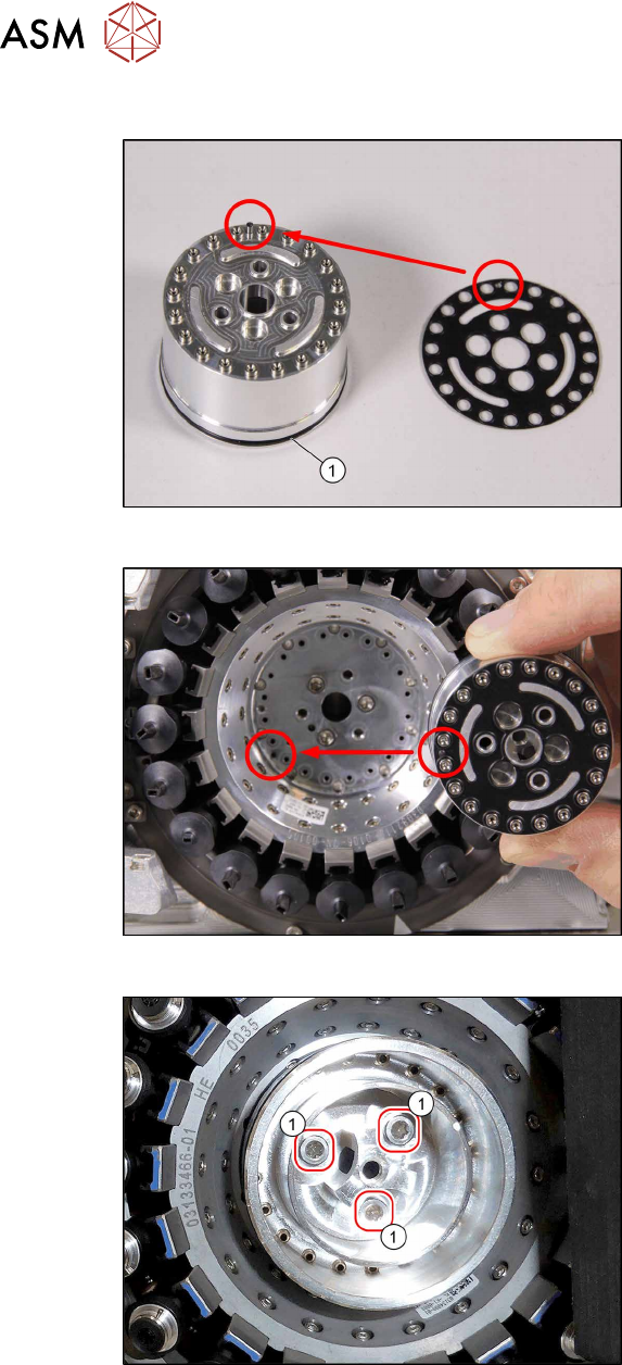
Fig.123: O‑Ring and sealing disc
► If the O-ring (1) is damaged, replace it
with a new one.
► Correctly position the sealing disc on
the aperture ring. Make sure all open-
ings are aligned. Pay attention to the
pin.
Fig.124: Inserting the aperture ring
► Position the aperture ring and sealing
disc correctly in the star carrier. Pay at-
tention to the pin.
Fig.125: Fasten the aperture ring
► Vacuum pump operation with aper-
ture ring only: Fix the aperture ring
with the three fastening screws (1)
(TX10, M3x10, torque 1.3 Nm).
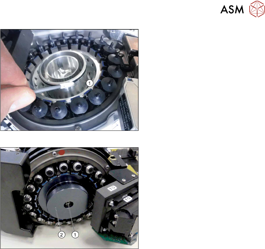
► Venturi operation with holding cir-
cuit only: Fix the holding circuit into
place with the three fastening screws.
(TX10, M3x10, torque 0.25Nm
).
7 Appendix
7.4 Excerpts from the service manual
Assembly Instructions / Montageanleitung SIPLACE X-Series S (from/ab Hxxxx) Option Vacuum Pump 02/2021 205
Fig.126: Greasing the O-ring
► Grease the O-ring. To do this, use a
cleaning stick coated with "Isoflex To-
pas 5051 50ml (green)".
Fig.127: Fitting the cover
► Vacuum pump operation:
Fit the cover (2)
with a screw(1) (TX10,
M4x14, torque 1.3Nm
).
► Venturi operation only:
Fit the silencer. Tighten the screw
fastening the silencer by hand
.
7 Appendix
7.4 Excerpts from the service manual
206 Assembly Instructions / Montageanleitung SIPLACE X-Series S (from/ab Hxxxx) Option Vacuum Pump 02/2021
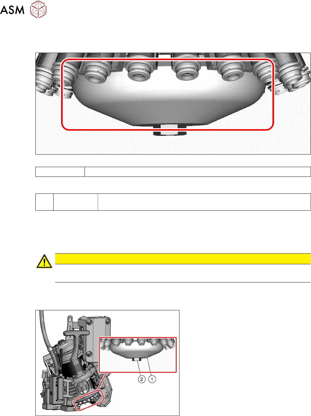
7.4.7.2 Replacing the silencer (venturi mode only)
Parts
Fig.128: Silencer
03043707-xx Silencer
Equipment and tools
T --- Tools for removing/fitting and calibrating the placement head, if needed
(see also the service manual for your machine)
Preparation
► Remove the head from the machine. For details about removing and fitting the placement
head, refer to the service manual for your machine.
Fit the head on the head mount [03056231‑xx].
CAUTION
Camera
► Make sure that you do not damage or contaminate the camera lens system.
► Make sure that the component sensor protective cap is fitted.
Removal
Fig.129: Silencer
► Remove the screw (2) fastening the si-
lencer (1)
.
► Carefully lever out the silencer.
Installation
► Follow the removal instructions in reverse order for installation. Also observe the following
instructions:
– Carefully press the new silencer down, onto the holding circuit.
– Carefully hand-tighten the screw fastening the silencer.