00197471-03_Service Manual Internal WPC5_6, EN_01-2019.pdf - 第101页
Service Manual In ternal WPC5 / WPC6 Page 3-101 ➢ Mark the exact pos ition of the light barrier on th e metal bracket, as we ll as the position from the metal bracket on t he tower cov er. ➢ Loosen the two fasten ing s…
Service Manual Internal WPC5 / WPC6
Page 3-100
3.7.12 Sensor 4a / 4b Crash Light Barrier Feed axis vs. Tower
Spare Part
• Crash Light Barrier Feed axis vs. Tower [03056927-xx]
Removal / Installation
WARNING
Special adjustmend necessary
After exchange of the Light barrier, accurate adjustments have to be done, using the „Adjustment
and testing jig WPC4-6 compl.“ [03093396-01].
This work has to be done by trained people (best SIPLACE Service).
See 5.6 Setting the crash light barrier on the tower [
➙
5-165]
NOTICE
Spare Part
The transmitter and receiver of the relevant crash light barrier are stocked as one spare
part with one part number.
Depending on the error occurring, you may need to replace the transmitter and receiver
together.
2
2
Service Manual Internal WPC5 / WPC6
Page 3-101
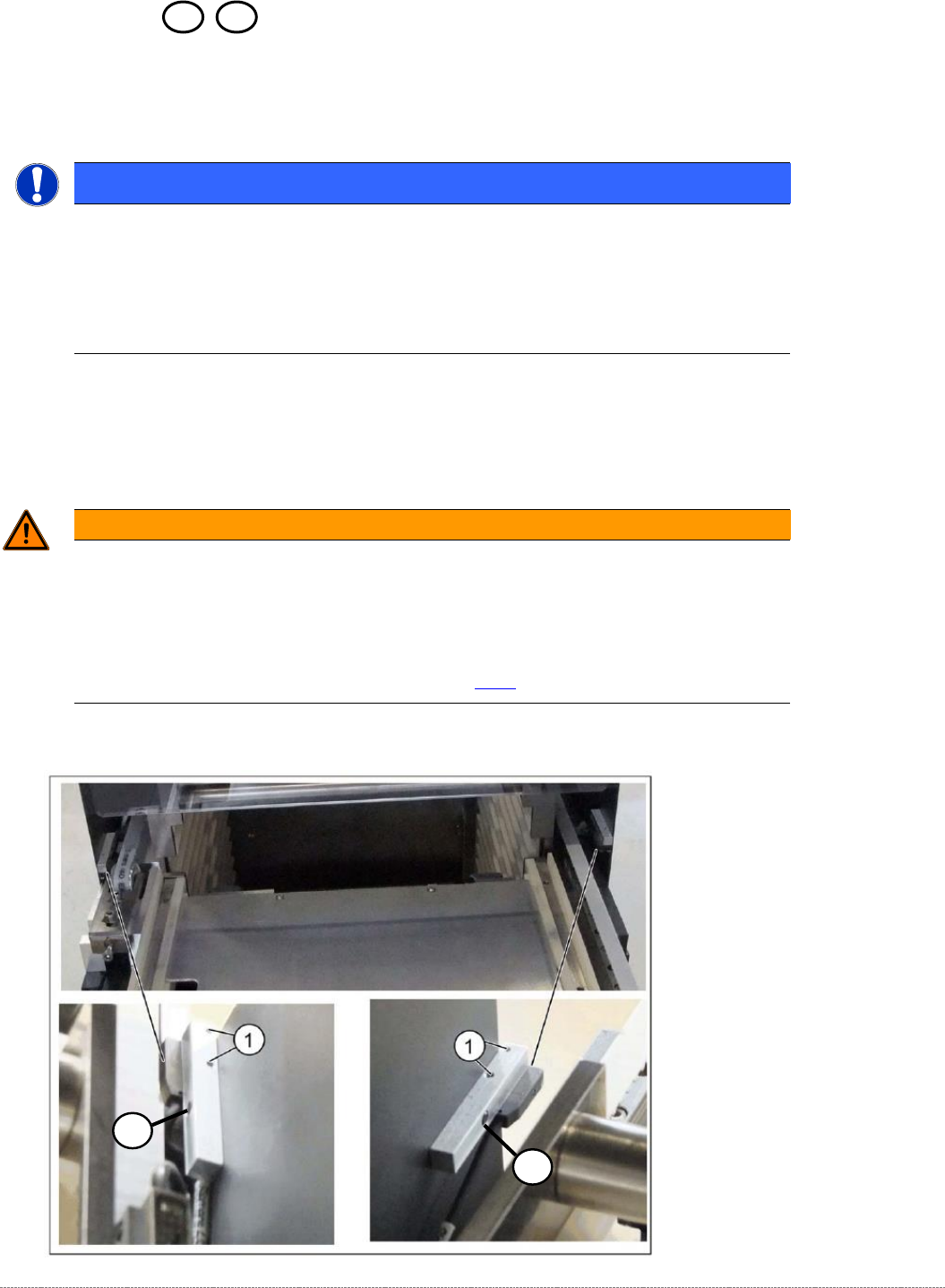
➢ Mark the exact position of the light barrier on the metal bracket, as well as the position from
the metal bracket on the tower cover.
➢ Loosen the two fastening screws of the Light Barrier Receiver/Sender (1).
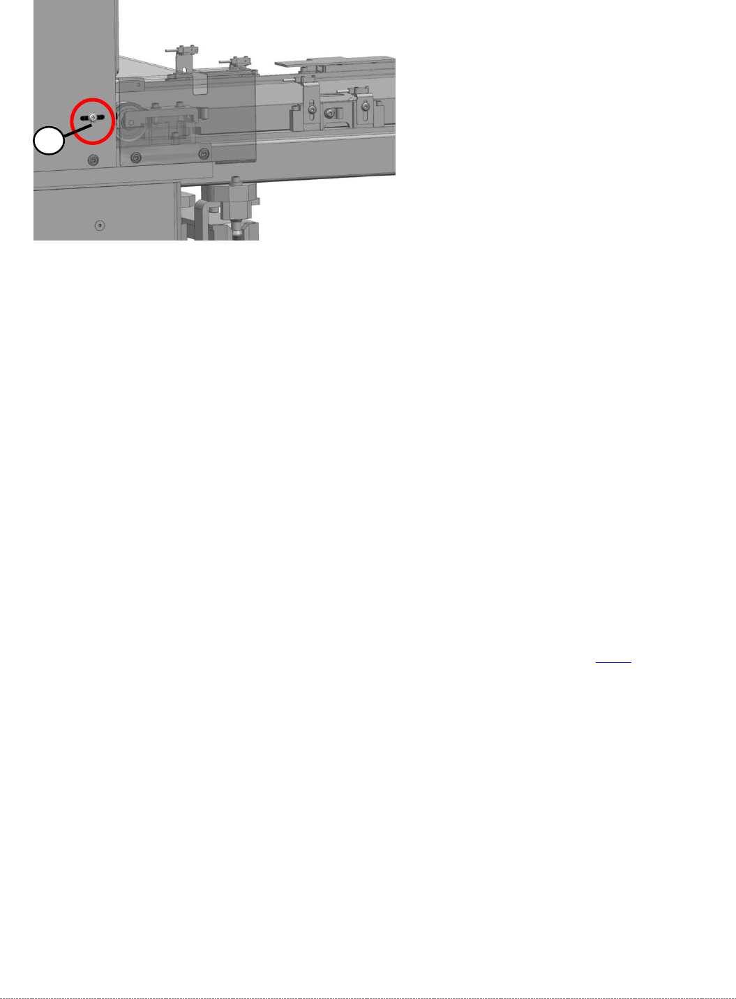
➢ The Light Barrier is mounted on a metal bracket, which is set on the Tower Cover with a
screw from outside the cover (2).
➢ Loosen the cable clamps and remove the cable ties.
➢ Unthread the connection cable as far as the control unit back plane and unplug it from the
terminal strip.
The cable is guided on a support plate between Tower and Tower’s Cover and then moved
below the feed axis.
➢ Fit the new crash light barrier at the marked installation position.
➢ Restore the electrical connection and fix the connection cable into place.
Settings
➢ Set the crash light barrier. See "5.6
Setting the crash light barrier on the tower
" [➙ 5-165].
2
Service Manual Internal WPC5 / WPC6
Page 3-102
3.7.13 Sensor 12 Reference Proximity Switch Load axis
Spare Part
• Reference point proximity switch load axis [03056947-xx]
Removal / Installation
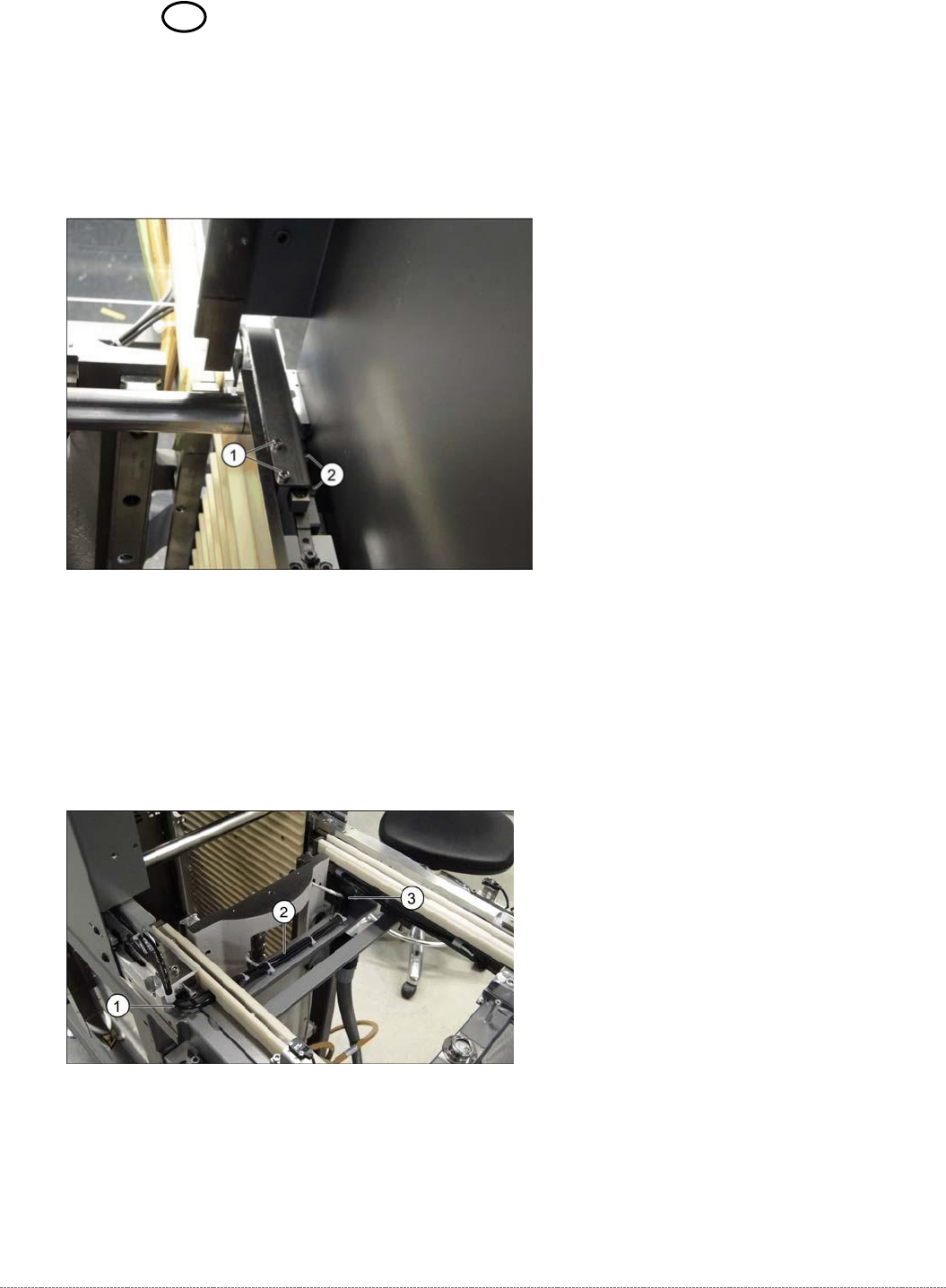
➢ Loosen the two screws (1) fastening the sensor fixture bracket and unthread the cable.
➢ Unthread the connection cable as far as the control unit back plane and unplug it from the
terminal strip.
➢ Loosen the two screws (2) fastening the sensor to the fixture bracket and then remove the
sensor.
➢ Screw the new sensor to the fixture bracket (2).
➢ Fix the bracket into the tower with the two screws which you removed (1).
➢ Run the cable out of the tower, under the feed axis and along to the other side (1 to 3) and
up to the back plane of the control unit. Fix the cable into place with cable ties.
➢ Restore the electrical connection and fix the connection cable into place.