00197471-03_Service Manual Internal WPC5_6, EN_01-2019.pdf - 第153页
Service Manual In ternal WPC5 / WPC6 Page 5-153 5.5 Setting the po sition of the gu ide rails Make alignm ent marks on all the guide rails of the tower as shown be low. Figure 5.8: Mar king the cham fers of the guide r…
Service Manual Internal WPC5 / WPC6
Page 5-152
Push this up to the stopper of the gauge.
Then tighten the two screws again.
Figure 5.7: Setting the spring stopper
WARNING
Caution:
Now remove the “Jig stopper spring cmpl." [03093820-01].
If you do not do so, there is an increased risk of a crash!
Service Manual Internal WPC5 / WPC6
Page 5-153
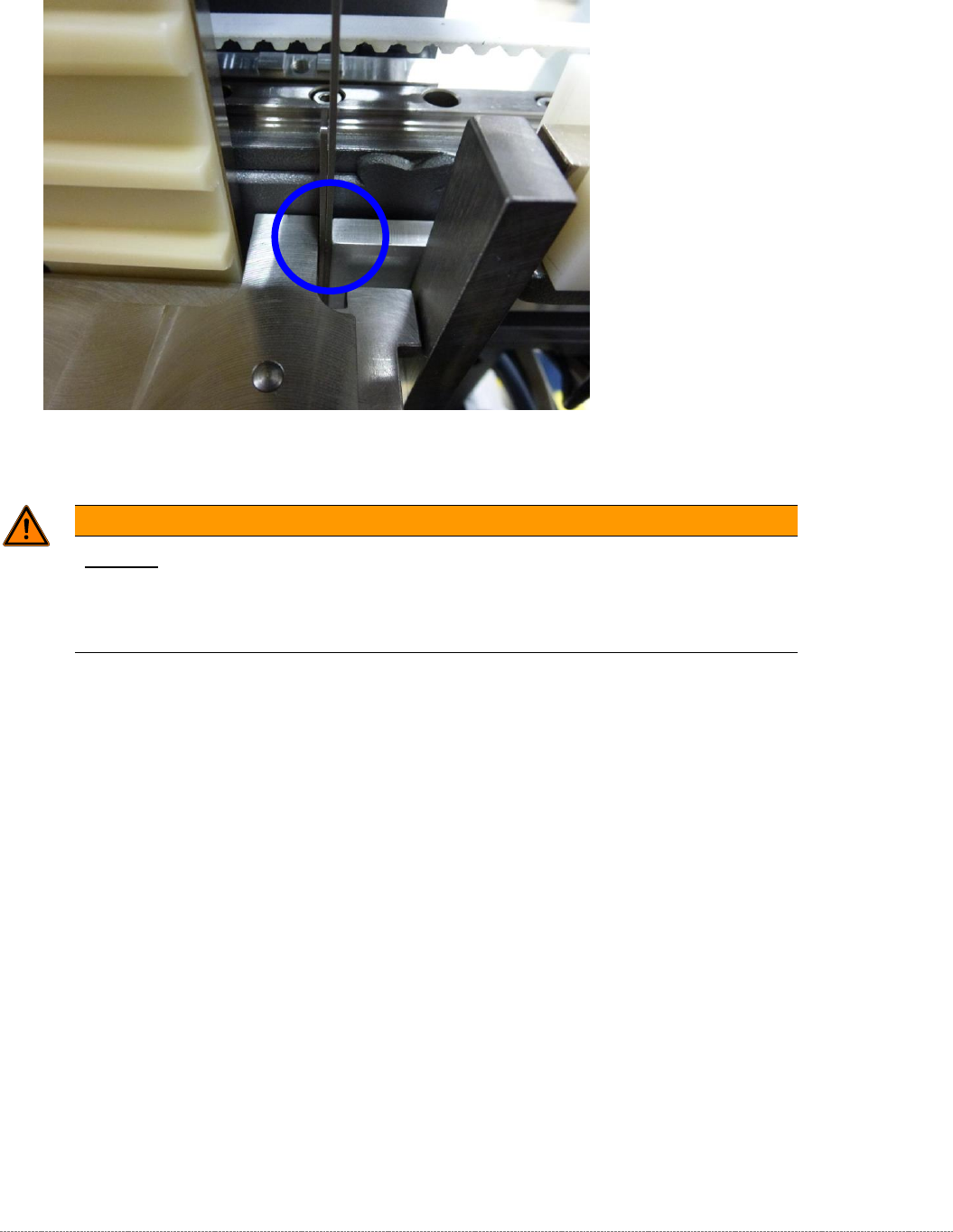
5.5 Setting the position of the guide rails
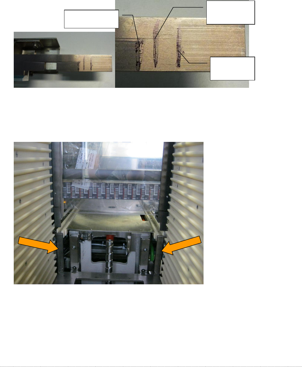
Make alignment marks on all the guide rails of the tower as shown below.
Figure 5.8: Marking the chamfers of the guide rails
5.5.1 Front, bottom guide rail (transition to feed axis)
Figure 5.9: Front, bottom guide rails
Move the tower further down until the gauge is at the same height as the alignment marks for the
start of the chamfer of the bottom guide rails.
The left-hand rail is installed slightly lower than the right-hand rail.
You should therefore always position the lifting axis in such a way that the gauge is aligned with the
height of the marking on the left-hand guide rail!
At the start of the
top chamfer
At the start of
the bottom
chamfer
Centrally
between the
two chamfers
Service Manual Internal WPC5 / WPC6
Page 5-154
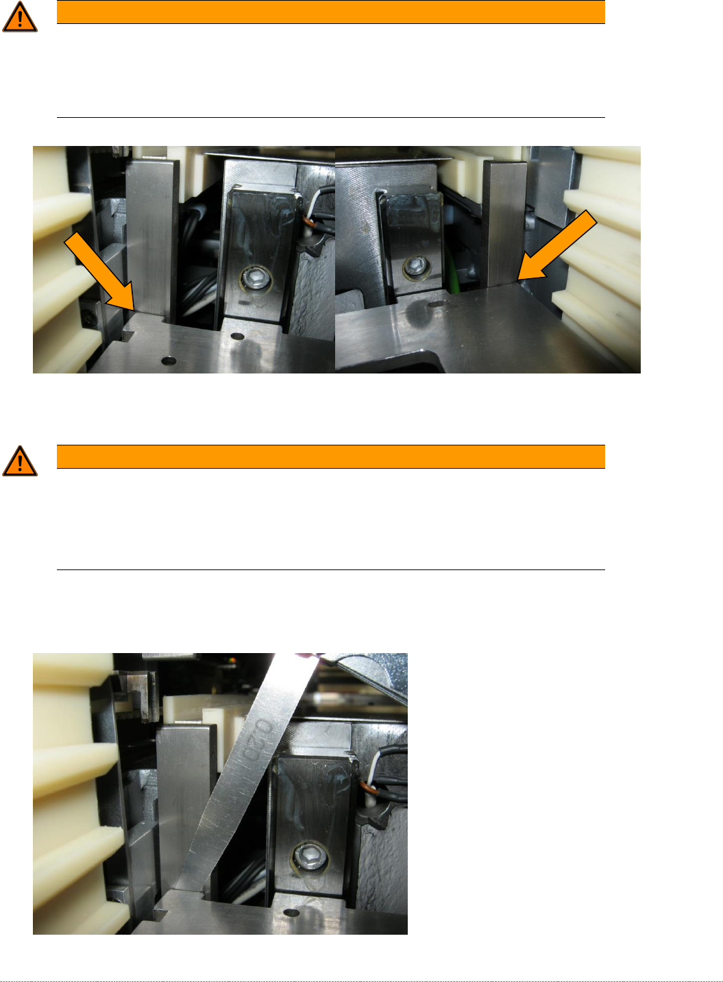
WARNING
Alignment of the gauge
If you position the gauge to align with the right-hand rail, and then set the gap for both
sides, the gap at the left-hand rail will be incorrect because you will be positioning the
feeler gauge on the chamfer of the guide rail.
Figure 5.10: Abstand Führungsleiste unten, vorne, obere Position überprüfen, 0,2mm.
WARNING
Do not displace the gauge
Although the gauge is clamped in the tower, it is not clamped tightly.
When you are performing this work, in particular when you are inserting the feeler gauge,
make sure that you do not displace the gauge.
Now use a feeler gauge to set a gap of 0.2 mm between the guide rail and the baseplate of the
gauge.
Figure 5.11: Gap at the front, bottom guide rail, checking the top position.