00197471-03_Service Manual Internal WPC5_6, EN_01-2019.pdf - 第23页
Service Manual In ternal WPC5 / WPC6 Page 3- 23 3.4.3 Replace the Drive Toothed Belt Spare Part: • Drive toothed belt 16T5/330 [03047689- 01] Removal / Install ation ➢ Loosen the two motor s upport fastenin g screws (3…
Service Manual Internal WPC5 / WPC6
Page 3-22
➢ Loosen the two motor support fastening screws (3) sealed with locking varnish.
➢ Loosen (do not remove) the tensioning screw (2) on the tensioning device. This relaxes the
drive toothed belt.
➢ Loosen and remove the 2 fastening screws (3) and then remove the drive motor with motor
support.
➢ Make sure that the drive toothed belt (4) is not buckled or damaged.
➢ Mark the installation position of the drive motor on the motor support.
➢ Loosen the 4 drive motor fastening screws (6) on the motor support.
➢ Fit the new drive motor with the 4 fastening screws (6) to the motor support. Observe the
original installation position.
➢ Move the motor and motor support into the installation position and run the drive toothed
belt (4) around the motor pinion and around the deflection pulley (5).
➢ Reconnect the electrical connections with the motor. When fitting, note that there is an anti-
twist lock (notch) present. Tighten the connection appropriately.
➢ Tension (pretension) the drive toothed belt at the slot provided, with the help of the motor
support. Make sure that the drive toothed belt (4) is not buckled or damaged.
➢ Loosely fix the motor support and drive motor into the installation position, with the 2
fastening screws (3).
➢ Set the final belt tension. To do this, tension the drive toothed belt at the tensioning device,
with the help of the tensioning screw (2). This moves the motor support accordingly in the
slots.
⇨ Setting value: Set the belt tension to 265 Hz +/- 5 Hz.
➢ Tighten the 2 fastening screws (3) on the motor support, check the belt tension and adjust
where necessary.
➢ Seal the 2 fastening screws (3) with locking varnish.
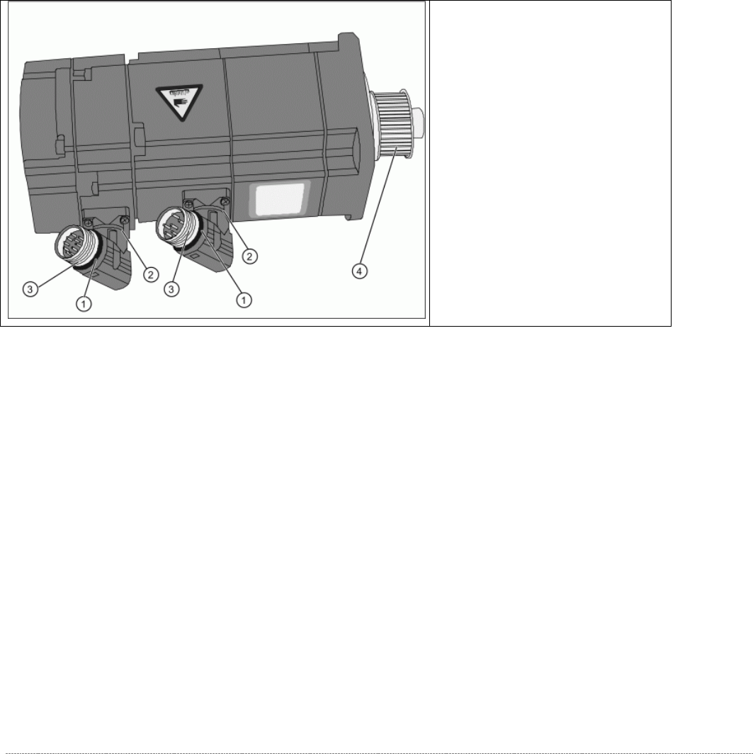
Overview of motor
(1) O-Ring
(2) Rotary connection
(3) Thread
(4) Motor pinion
➢ The motor connections can be
rotated by hand. Rotate the
connections to the position the
motor was installed in before.
➢
Grease the thread (3) and the O-
rings (1) with a little Vaseline.
Service Manual Internal WPC5 / WPC6
Page 3-23
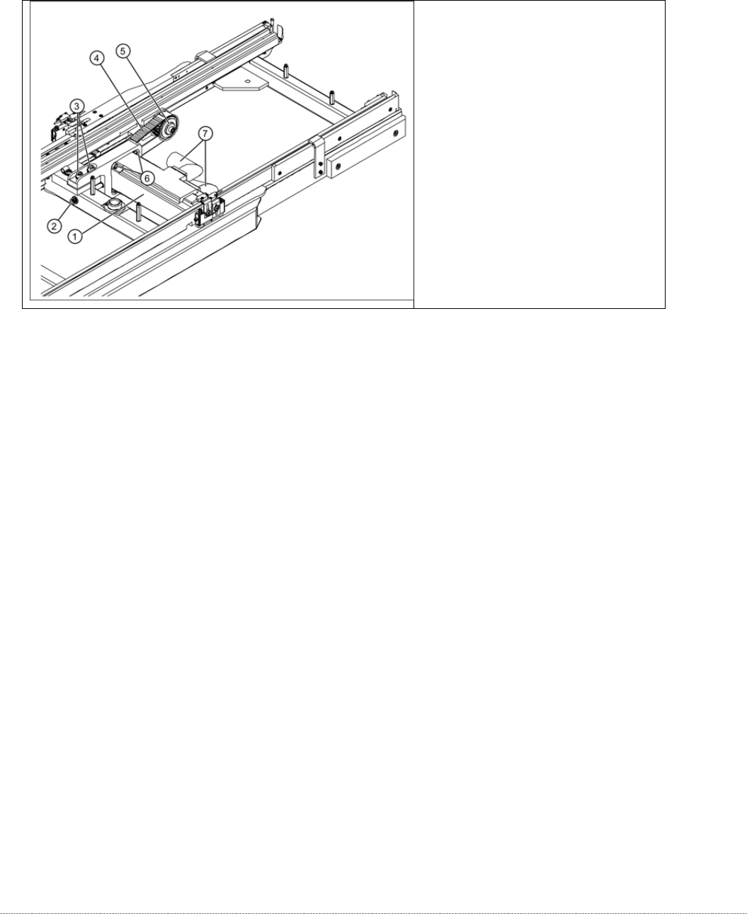
3.4.3 Replace the Drive Toothed Belt
Spare Part:
• Drive toothed belt 16T5/330 [03047689-01]
Removal / Installation
➢ Loosen the two motor support fastening screws (3) sealed with locking varnish.
➢ Loosen (do not remove) the tensioning screw (2) on the tensioning device. This relaxes the
drive toothed belt (4).
➢ Loosen and remove the 2 fastening screws (3) so that you have enough play to move the
motor properly and then remove the old drive toothed belt (4).
➢ Move the motor and motor support (1) into the installation position and run the drive toothed
belt (4) around the motor pinion (2) and around the deflection pulley (5). Make sure that the
drive toothed belt (4) is not buckled or damaged.
➢ Tension (pretension) the drive toothed belt at the slot provided, with the help of the motor
support.
➢ Loosely fix the motor support and drive motor into the installation position, with the 2
fastening screws (3).
➢ Set the final belt tension. To do this, tension the drive toothed belt at the tensioning device,
with the help of the tensioning screw (2). This moves the motor support accordingly in the
slots.
⇨ Setting value: Set the belt tension to 265 Hz +/- 10 Hz.
➢ Tighten the 2 fastening screws (2) on the motor support, check the belt tension and adjust
where necessary.
➢ Seal the 2 fastening screws (3) with locking varnish.
Overview
(1) Motor Feed axis compl.
[03047364-01]
(2) Tensioning screw
(3) 2 x motor support fastening screws
(4) Toothed belt for the drive
(5) Deflection pulley
Service Manual Internal WPC5 / WPC6
Page 3-24
3.4.4 Replace the Driver Unit
Spare Part:
• Tappet gripper 359 lg cpl. [03069215-xx]
Removal / Installation
➢ Move the driver feed axis with the toothed belt into a suitable position for service work (at
the front, in the transfer area).
➢ Loosen the two screws (1) fastening the cover and remove the cover.
➢ Loosen the four screws (2) fastening the driver unit. The two ends of the toothed belt are
fixed to this.
➢ Carefully remove the driver unit.
➢ Follow the removal instructions in reverse order for installation.
➢ Align the driver unit (see "3.4.4.1 Align the Driver Unit" [➙ 3-24]).
➢ Check the belt tension (see "3.4.6 Setting the Feed Axis Belt Tension” [➙ 3-28]).
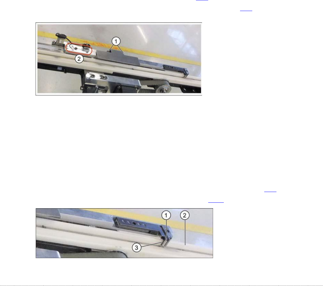
3.4.4.1 Align the Driver Unit
The driver unit must be adjusted so that it is straight (adjust at fastening screws). Make sure that
it does not rub against any parts or jam at any point of the travel range.
➢ Set the driver (1) to a distance of approx. 0.5 mm (3) to the white plastic guidance (2).
➢ Push the driver back and forth along the travel range, to check that it does not rub against
any parts or jam at any point.
➢ Set the correct belt tension. See also "3.4.6 Setting the Feed Axis Belt Tension" [➙ 3-28].
➢ Calibrate the feed axis (see "4.2 Calibrating the Feed Axis" [➙ 4-126]).