00197471-03_Service Manual Internal WPC5_6, EN_01-2019.pdf - 第24页
Service Manual In ternal WPC5 / WPC6 Page 3- 24 3.4.4 Replace the Driver Unit Spare Part: • Tappet gripper 359 lg cpl. [03069215- xx] Removal / Install ation ➢ Move the driver fee d axis with the toothed be lt into a s…
Service Manual Internal WPC5 / WPC6
Page 3-23
3.4.3 Replace the Drive Toothed Belt
Spare Part:
• Drive toothed belt 16T5/330 [03047689-01]
Removal / Installation
➢ Loosen the two motor support fastening screws (3) sealed with locking varnish.
➢ Loosen (do not remove) the tensioning screw (2) on the tensioning device. This relaxes the
drive toothed belt (4).
➢ Loosen and remove the 2 fastening screws (3) so that you have enough play to move the
motor properly and then remove the old drive toothed belt (4).
➢ Move the motor and motor support (1) into the installation position and run the drive toothed
belt (4) around the motor pinion (2) and around the deflection pulley (5). Make sure that the
drive toothed belt (4) is not buckled or damaged.
➢ Tension (pretension) the drive toothed belt at the slot provided, with the help of the motor
support.
➢ Loosely fix the motor support and drive motor into the installation position, with the 2
fastening screws (3).
➢ Set the final belt tension. To do this, tension the drive toothed belt at the tensioning device,
with the help of the tensioning screw (2). This moves the motor support accordingly in the
slots.
⇨ Setting value: Set the belt tension to 265 Hz +/- 10 Hz.
➢ Tighten the 2 fastening screws (2) on the motor support, check the belt tension and adjust
where necessary.
➢ Seal the 2 fastening screws (3) with locking varnish.
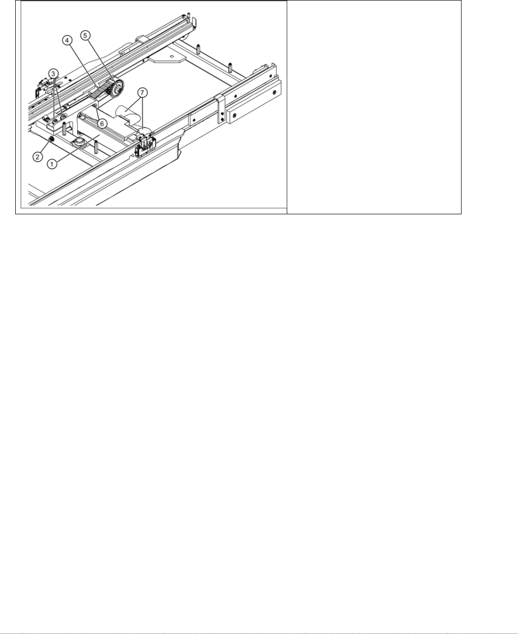
Overview
(1) Motor Feed axis compl.
[03047364-01]
(2) Tensioning screw
(3) 2 x motor support fastening screws
(4) Toothed belt for the drive
(5) Deflection pulley
Service Manual Internal WPC5 / WPC6
Page 3-24
3.4.4 Replace the Driver Unit
Spare Part:
• Tappet gripper 359 lg cpl. [03069215-xx]
Removal / Installation
➢ Move the driver feed axis with the toothed belt into a suitable position for service work (at
the front, in the transfer area).
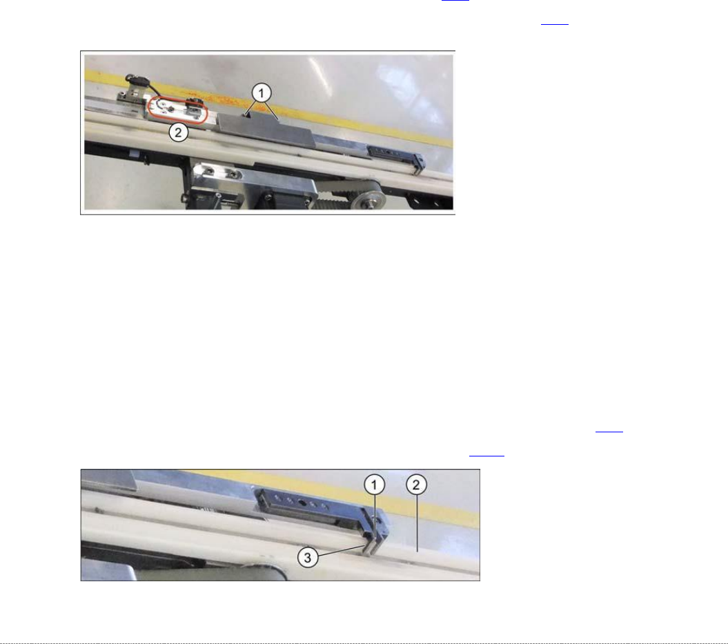
➢ Loosen the two screws (1) fastening the cover and remove the cover.
➢ Loosen the four screws (2) fastening the driver unit. The two ends of the toothed belt are
fixed to this.
➢ Carefully remove the driver unit.
➢ Follow the removal instructions in reverse order for installation.
➢ Align the driver unit (see "3.4.4.1 Align the Driver Unit" [➙ 3-24]).
➢ Check the belt tension (see "3.4.6 Setting the Feed Axis Belt Tension” [➙ 3-28]).
3.4.4.1 Align the Driver Unit
The driver unit must be adjusted so that it is straight (adjust at fastening screws). Make sure that
it does not rub against any parts or jam at any point of the travel range.
➢ Set the driver (1) to a distance of approx. 0.5 mm (3) to the white plastic guidance (2).
➢ Push the driver back and forth along the travel range, to check that it does not rub against
any parts or jam at any point.
➢ Set the correct belt tension. See also "3.4.6 Setting the Feed Axis Belt Tension" [➙ 3-28].
➢ Calibrate the feed axis (see "4.2 Calibrating the Feed Axis" [➙ 4-126]).
Service Manual Internal WPC5 / WPC6
Page 3-25
3.4.5 Replace the Feed Axis Toothed Belt
Spare Part
• Toothed belt 10T5/2120E [03047690-01]
Preparations
➢ Move the tower into the refill position.
➢ Remove all waffle pack tray carriers (WPTCs) from the tower.
➢ Move the tower downwards.
⇨ Check sensors and functions ⇨ Check sensors and functions of specific components ⇨
⇨ Location ⇨ Check functions for WPC ⇨ Move into transport position.
➢ Undock the WPC from the SIPLACE machine and move it to a suitable position for service
work.
➢ Switch the WPC off at the main switch.
➢ Unplug from the power supply and secure the WPC to prevent unauthorized reactivation.
➢ Remove the cover of the NSM module (see "3.5.1.1 Remove the Cover on the Load Unit"
[➙ 3-33]).
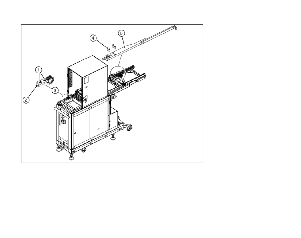
Removal / Installation
➢ Move the feed axis driver with the toothed belt into a suitable position for service work (at the
front, in the transfer area).
➢ Loosen the two fastening screws (1) sealed with locking varnish, at the tensioning device
with the deflection pulley (3).
➢ Loosen (do not remove) the tensioning screw (2) - sealed with locking varnish - on the
tensioning device. This relaxes the toothed belt.