00197471-03_Service Manual Internal WPC5_6, EN_01-2019.pdf - 第94页
Service Manual In ternal WPC5 / WPC6 Page 3- 94 3.7.8 Sensor 6 Reference Sensor " Lifting axis“ Spare Part • Reference point proxim ity switch for lifting axis [03047278-0 1] Removal / Install ation ➢ Loosen the t…

Service Manual Internal WPC5 / WPC6
Page 3-93
For the light barrier LB Type 1:
The status of the crash light barrier will be shown by the integrated LED:
• Red LED shines = not triggered (normal mode)
• Red LED does not shine = triggered (the light beam is interrupted - crash situation)
• Green LED shines = ready for operation/stability display (optimum light barrier setting)
• Green LED does not shine = ready for operation/stability display (no optimum light barrier
setting)
• LED shines red and green = correct setting (the laser beam is not interrupted)
For the light barrier LS TYP 2 :
The Status of the ligth barrier is shown on the display (7 segment) of the control unit, as well as
with the LED beside the display.
• LED on (orange) = normal function (light beam is not interrupted)
• LED off = activated (light beam is interrupted – Crash situation)
The displayed value is in normal function higher than 2500.
The threshold, at which the unit switches (LED gets off), is at about 500.
=> at 100% interruption = 0,
Step 1: setting the height
➢ Position the setting gauge with the throughout height setting on the waffle-pack tray carrier,
before the relevant transmitter/receiver:
⇨ Description signals (LED, values), see above.
➢ Move the gauge or the waffle-pack tray carrier to the trigger height setting.
➢ Check whether the crash light barrier beam is interrupted at the trigger height setting or not.
➢ Place the "Setting gauge crash WPC4 LS-6 (level)" [03093895-02] on the other two
positions. The crash beam sensor must trigger safe here.
➢ Repeat the steps described until the crash light barriers are set to the correct height and
switch reliably at all trigger points over the entire area.
Step 2: function test
➢ Check that the correct outputs are switched.
Go to the main software view and open the menu function:
⇨ Sensors and Functions ⇨ Location ⇨ Check functions for WPC ⇨ Advanced functions ⇨
⇨ WPC E/A Ports.
check that the
Crash sensor for normal components
or
Crash sensor for
high components
option is enabled
.
Service Manual Internal WPC5 / WPC6
Page 3-94
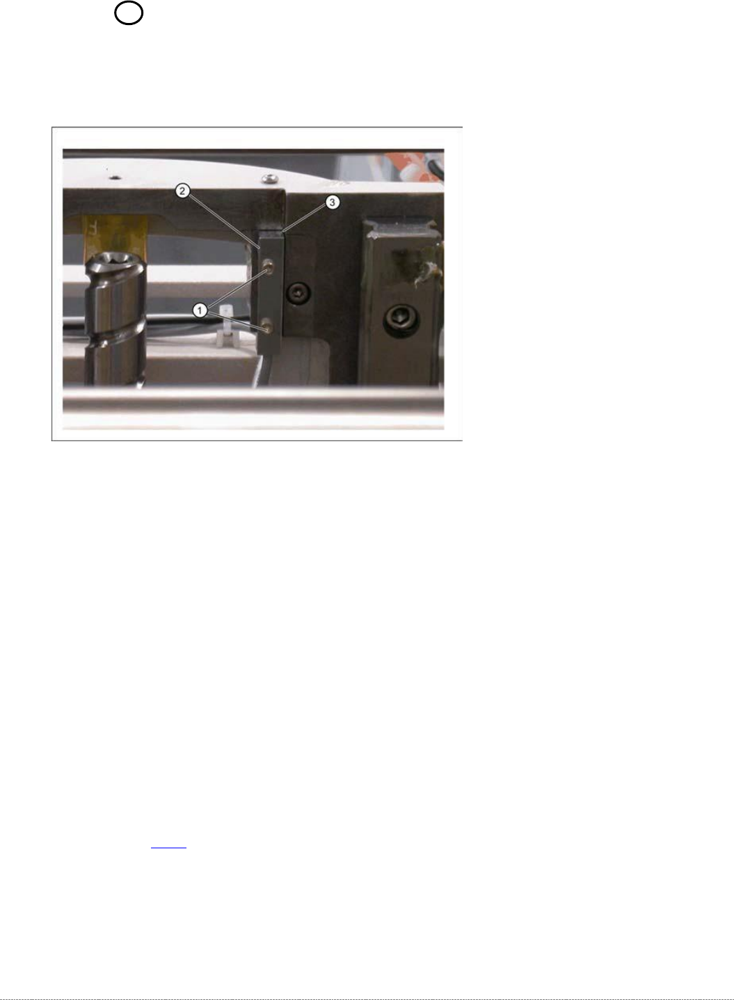
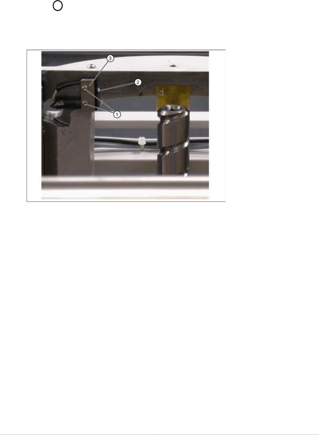
3.7.8 Sensor 6 Reference Sensor "Lifting axis“
Spare Part
• Reference point proximity switch for lifting axis [03047278-01]
Removal / Installation
➢ Loosen the two fastening screws (1) on the reference sensor.
➢ Loosen the cable clamps and remove the cable ties.
➢ Unthread the connection cable as far as the control unit back plane and unplug it from the
terminal strip.
➢ Fit the reference sensor so that the sensor surface (2) points to the side.
➢ Align the reference sensor parallel to the right-hand and top stopper edges (3).
➢ Restore the electrical connection and fix the connection cable into place.
Settings
➢ Check the function and correct position of the reference sensor.
➢ To do this, open the following function in the main view:
⇨ Sensors and Functions ⇨ Location ⇨ Check functions for WPC ⇨ Advanced functions.
➢ Select the
Lifting axis
button in the Axis entry field.
➢ Select the
Reference bero
button in the entry field (see "4.2.3 Reference Proximity Switch
(Bero)" [➙4-129]).
⇨ The lifting axis is moved, approaches the reference sensor and determines the reference
point.
⇨ The calculated value will be shown and can then be saved with the
Commit
button.
➢ If an error message appears, If necessary, correct the mechanical position of the limit switch
with the help of the slot (2) and repeat the measurement procedure.
Service Manual Internal WPC5 / WPC6
Page 3-95
3.7.9 Sensor 5 Top Lifting axis limited switch
Spare Part
• Top lifting axis limit switch [03047279-01]
Removal / Installation
➢ Mark the exact position of the limit switch.
➢ Loosen the two fastening screws (1) on the limit switch.
➢ Remove the fixture plate (3).
➢ Loosen the cable clamps and remove the cable ties.
➢ Unthread the connection cable as far as the control unit back plane and unplug it from the
terminal strip.
➢ Fit the new limit switch.
➢ Fit the new limit switch with fixture plate (3) at the marked installation position.
➢ Restore the electrical connection and fix the connection cable into place.