00197471-03_Service Manual Internal WPC5_6, EN_01-2019.pdf - 第32页
Service Manual In ternal WPC5 / WPC6 Page 3- 32 3.5 Driv e Unit Load Axis (WPC6 Only) 3.5.1 Preparations Tools Required • W ater pump pliers • Standard tool with set of Allen wrenches • Setting gauge, sm all [03052363-…
Service Manual Internal WPC5 / WPC6
Page 3-31
➢ Remove all screws from the guide rails and lift off the rails.
➢ If necessary, also remove the reference sensor and the load axis crash light barriers.
➢ Clean the contact surface with ethanol, before inserting the new guide rail.
➢ Position the new guide rail in place, press it against the stop edge and then loosely tighten
the screws. Make sure that the screws are centered in the holes.
➢ Tighten the screws. Start in the middle. There is no need to observe a specific torque. You
do not need to seal the screws with locking varnish.
➢ Make sure that the whole length of the guide rail lies against the stop edge.
➢ Fit the clamping unit.
There is no need to observe a specific torque. You do not need to seal the screws with
locking varnish.
➢ Continue by following the removal procedure in reverse order (see "3.5.5 Replacing the
Driver Assembly [03053436-xx]" [➙ 3-43] for WPC 6 and "3.4.5 Replacing the Feed Axis
Toothed Belt” [03047690-xx]" [➙ 3-25]).
See also...
@
3.4.4.1
Align the Driver Unit [➙ 3-24]
@
3.4.6
Setting the Feed axis Belt Tension [
➙
3-28]
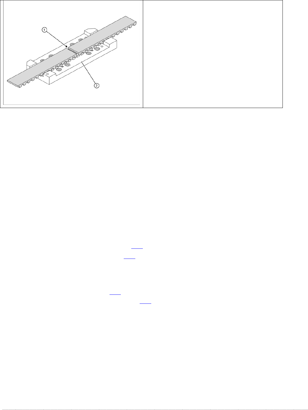
➢ Loosen the toothed belt clamping unit (1) from
the guide carriage.
➢ To do this, remove the 8 screws at 2.

Service Manual Internal WPC5 / WPC6
Page 3-32
3.5 Drive Unit Load Axis (WPC6 Only)
3.5.1 Preparations
Tools Required
• Water pump pliers
• Standard tool with set of Allen wrenches
• Setting gauge, small [03052363-xx]
• Belt tension measuring device [00326015-xx] with instruction guide
Prerequisite
➢ Move the tower into the refill position.
➢ Remove all waffle pack tray carriers (WPTCs) from the tower.
➢
Move the tower downwards.
⇨ Check sensors and functions ⇨ Check sensors and functions of specific components ⇨ Location ⇨
⇨ Check functions for WPC ⇨ Move into transport position
➢ Switch the WPC off at the main switch.
➢ Unplug from the power supply and secure the WPC to prevent unauthorized reactivation.
➢ Undock the WPC from the SIPLACE machine and move it to a suitable position for service
work.
➢ Remove the cover on the load unit (see "3.5.1.1 Removing the Cover on the Load Unit" [➙
3-33]).
➢ Remove the hand guard from the feed axis (bridge cover) (see "3.5.1.3 Removing the Feed
Axis Hand Guard" [➙ 3-34]).
See also...
@
3.5.1.4
Loosing the tension of the load Axis Drive Belt [➙ 3-34]
@
3.5.1.2
Remove the Right Side Cover from the WPC [
➙
3-33]
Service Manual Internal WPC5 / WPC6
Page 3-33
3.5.1.1 Remove the Cover on the Load Unit
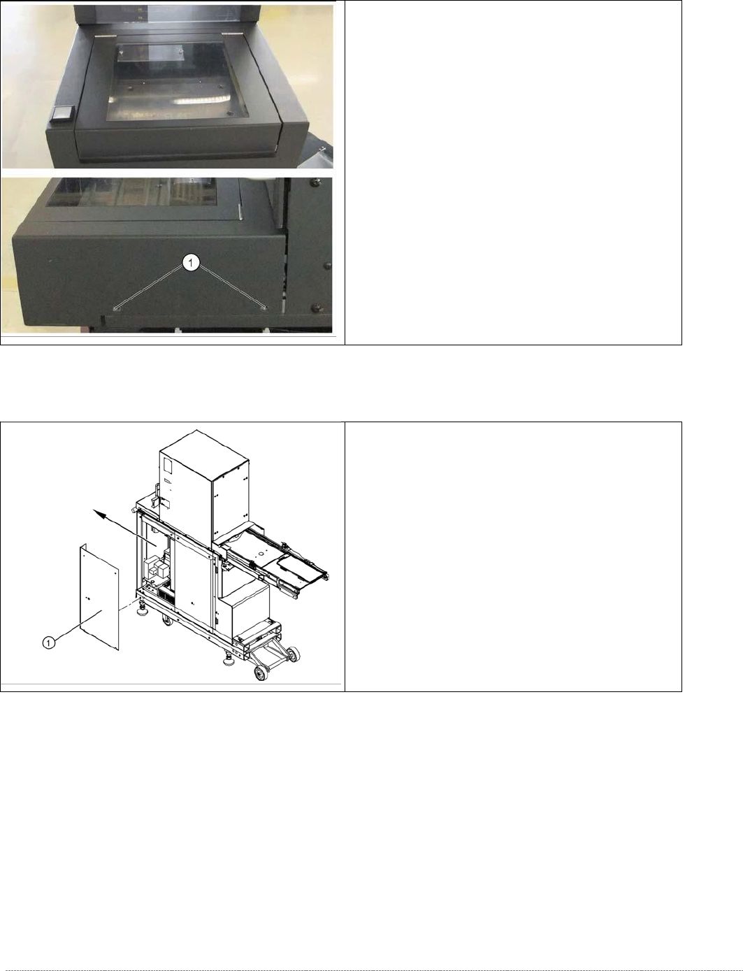
3.5.1.2 Remove the Right Side Cover from the WPC
➢ Loosen the two fastening screws (1) on the left
and right sides of the cover and lift off the
cover.
➢ Unplug the two cable connectors X1j and X2j.
➢ Remove the ground lead from the cover plate.
➢
Remove the four fastening screws from the right
side cover (1) and then take off the cover.